Products: ABAQUS/Standard ABAQUS/Explicit ABAQUS/CAE
A general shell section:
is used when numerical integration through the thickness of the shell is not required;
can be associated with linear elastic material behavior or, in ABAQUS/Standard, can invoke user subroutine UGENS to define nonlinear section properties in terms of forces and moments;
can be used to model an equivalent shell section for some more complex geometry (for example, replacing a corrugated shell with an equivalent smooth plate for global analysis); and
cannot be used with heat transfer and coupled temperature-displacement shells.
A general shell section can be defined as follows:
The section response can be specified by associating the section with a material definition or, in the case of a composite shell, with several different material definitions.
The section properties can be specified directly.
In ABAQUS/Standard the section response can be programmed in user subroutine UGENS.
You can define the shell section's mechanical response by specifying the thickness; the material reference; and the orientation of the section or, for a composite shell, the orientation of each of its layers. ABAQUS will determine the equivalent section properties. You must associate the section behavior with a region of your model.
The linear elastic material behavior is defined with a material definition (“Material data definition,” Section 16.1.2), which may contain linear elastic behavior (“Linear elastic behavior,” Section 17.2.1) and thermal expansion behavior (“Thermal expansion,” Section 20.1.2). The density (“Density,” Section 16.2.1) and damping (“Material damping,” Section 20.1.1) behavior can also be specified as described below; in ABAQUS/Explicit the density of the material must be defined. However, no nonlinear material properties, such as plastic behavior, can be included since ABAQUS will precompute the section response and will not update that response during the analysis. Dependence of the linear elastic material behavior on temperature or predefined field variables is not allowed.
The shell section response is defined by
![]()
![]()
To define a shell made of a single linear elastic material, you refer to the name of a material definition (“Material data definition,” Section 16.1.2) as described above. Optionally, you can define an orientation definition to be used with the section (“Orientations,” Section 2.2.5). In addition, you specify the shell thickness as part of the section definition. For continuum shell elements the specified thickness is used to estimate certain section properties, such as hourglass stiffness, that are later computed from the element geomerty.
You must associate this section behavior with a region of your model.
For homogeneous shells you can redefine the thickness, offset, section stiffness, and material orientation specified in the section definition on an element-by-element basis. See “Assigning element properties on an element-by-element basis,” Section 21.1.5.
| Input File Usage: | *SHELL GENERAL SECTION, ELSET=name, MATERIAL=name, ORIENTATION=name |
where the ELSET parameter refers to a set of shell elements. |
| ABAQUS/CAE Usage: | Property module:
Create Section: select Shell as the section Category and Homogeneous as
the section Type: Section integration: Before analysis:
Basic: Material: name
Assign |
You can define a shell made of layers with different linear elastic material behaviors. Optionally, you can define an orientation definition to be used with the section (“Orientations,” Section 2.2.5).
You specify the layer thickness; the name of the material forming this layer (as described above); and the orientation angle, ![]() , (in degrees) measured positive counterclockwise relative to the specified section orientation definition, where
, (in degrees) measured positive counterclockwise relative to the specified section orientation definition, where ![]() . If either of the two local directions from the specified section orientation is not in the surface of the shell,
. If either of the two local directions from the specified section orientation is not in the surface of the shell, ![]() is applied after the section orientation has been projected onto the shell surface. If you do not specify a section orientation,
is applied after the section orientation has been projected onto the shell surface. If you do not specify a section orientation, ![]() is measured relative to the default shell local directions (see “Conventions,” Section 1.2.2). The order of the laminated shell layers with respect to the positive direction of the shell normal is defined by the order in which the layers are specified.
is measured relative to the default shell local directions (see “Conventions,” Section 1.2.2). The order of the laminated shell layers with respect to the positive direction of the shell normal is defined by the order in which the layers are specified.
For continuum shell elements the thickness is determined from the element geometry and may vary through the model for a given section definition. Hence, the specified thicknesses are only relative thicknesses for each layer. The actual thickness of a layer is the element thickness times the fraction of the total thickness that is accounted for by each layer. The thickness ratios for the layers need not be given in physical units, nor do the sum of the layer relative thicknesses need to add to one. The specified shell thickness is used to estimate certain section properties, such as hourglass stiffness, that are later computed from the element geometry.
You must associate this section behavior with a region of your model.
| Input File Usage: | *SHELL GENERAL SECTION, ELSET=name, COMPOSITE, ORIENTATION=name |
where the ELSET parameter refers to a set of shell elements. |
| ABAQUS/CAE Usage: | Property module:
Create Section: select Shell as the section Category and Composite as the
section Type: Section integration: Before analysis
Assign |
You can define the section's mechanical response by specifying the general section stiffness and thermal expansion response—![]() ,
, ![]() ,
, ![]() and
and ![]() , as defined below—directly. Since this method then provides the complete specification of the section's mechanical response, no material reference is needed. Optionally, you can define
, as defined below—directly. Since this method then provides the complete specification of the section's mechanical response, no material reference is needed. Optionally, you can define ![]() , the reference temperature for thermal expansion.
, the reference temperature for thermal expansion.
You must associate this section behavior with a region of your model.
In this case the shell section response is defined by
![]()
![]()
are the forces and moments on the shell section (membrane forces per unit length, bending moments per unit length);
![]()
are the generalized section strains in the shell (reference surface strains and curvatures);
![]()
is the section stiffness matrix;
![]()
is a scaling modulus, which can be used to introduce temperature ![]() and field-variable
and field-variable ![]() dependence of the cross-section stiffness; and
dependence of the cross-section stiffness; and
![]()
are the section forces and moments caused by thermal strains.
![]()
![]()
is a scaling factor (the “thermal expansion coefficient”);
![]()
is the initial (stress-free) temperature at this point in the shell, defined by the initial nodal temperatures given as initial conditions (“Defining initial temperatures” in “Initial conditions,” Section 27.2.1); and
![]()
are the user-specified generalized stresses caused by a fully constrained unit temperature rise.
If the coefficient of thermal expansion, ![]() , is not a function of temperature, the value of
, is not a function of temperature, the value of ![]() is not needed. Note the distinction between
is not needed. Note the distinction between ![]() , the reference value used in defining
, the reference value used in defining ![]() , and the stress-free initial temperature,
, and the stress-free initial temperature, ![]() .
.
In these equations the order of the terms is
This method of defining the shell section properties cannot be used with variable thickness shells or continuum shell elements.
See “Laminated composite shells: buckling of a cylindrical panel with a circular hole,” Section 1.2.2 of the ABAQUS Example Problems Manual, for more information.
For conventional shell elements the section stiffness matrix, ![]() , can be redefined on an element-by-element basis. See “Assigning element properties on an element-by-element basis,” Section 21.1.5.
, can be redefined on an element-by-element basis. See “Assigning element properties on an element-by-element basis,” Section 21.1.5.
| Input File Usage: | *SHELL GENERAL SECTION, ELSET=name, ZERO= |
where the ELSET parameter refers to a set of shell elements. |
| ABAQUS/CAE Usage: | You cannot define the shell section properties directly in ABAQUS/CAE. |
In ABAQUS/Standard you can define the section response in user subroutine UGENS for the more general case where the section response may be nonlinear. User subroutine UGENS is particularly useful if the nonlinear behavior of the section involves geometric as well as material nonlinearity, such as may occur due to section collapse. If only nonlinear material behavior is present, it is simpler to use a shell section integrated during the analysis with the appropriate nonlinear material model.
You must specify a constant section thickness as part of the section definition or a continuously varying thickness by defining the thickness at the nodes as described below. Even though the section's mechanical behavior is defined in user subroutine UGENS, the thickness of the shell section is required for calculation of the hourglass control stiffness. You must associate this section behavior with a region of your model.
ABAQUS/Standard calls user subroutine UGENS for each integration point at each iteration of every increment. The subroutine provides the section state at the start of the increment (section forces and moments, ![]() ; generalized section strains,
; generalized section strains, ![]() ; solution-dependent state variables; temperature; and any predefined field variables); the increments in temperature and predefined field variables; the generalized section strain increments,
; solution-dependent state variables; temperature; and any predefined field variables); the increments in temperature and predefined field variables; the generalized section strain increments, ![]() ; and the time increment.
; and the time increment.
The subroutine must perform two functions: it must update the forces, the moments, and the solution-dependent state variables to their values at the end of the increment; and it must provide the section stiffness matrix, ![]() . The complete section response, including the thermal expansion effects, must be programmed in the user subroutine.
. The complete section response, including the thermal expansion effects, must be programmed in the user subroutine.
You should ensure that the strain increment is not used or changed in user subroutine UGENS for linear perturbation analyses. For this case the quantity is undefined.
| Input File Usage: | *SHELL GENERAL SECTION, ELSET=name, USER |
where the ELSET parameter refers to a set of shell elements. |
| ABAQUS/CAE Usage: | User subroutine UGENS is not supported in ABAQUS/CAE. |
If the section stiffness matrices are not symmetric, you can specify that ABAQUS/Standard should use its unsymmetric equation solution capability (see “Procedures: overview,” Section 6.1.1).
| Input File Usage: | *SHELL GENERAL SECTION, ELSET=name, USER, UNSYMM |
| ABAQUS/CAE Usage: | User subroutine UGENS is not supported in ABAQUS/CAE. |
Any number of constants can be defined to be used in determining the section behavior. You can specify the number of integer property values required, m, and the number of real (floating point) property values required, n; the total number of values required is the sum of these two numbers. The default number of integer property values required is 0, and the default number of real property values required is 0.
Integer property values can be used inside user subroutine UGENS as flags, indices, counters, etc. Examples of real (floating point) property values are material properties, geometric data, and any other information required to calculate the section response in UGENS.
The property values are passed into user subroutine UGENS each time the subroutine is called.
| Input File Usage: | *SHELL GENERAL SECTION, ELSET=name, USER, I PROPERTIES=m, PROPERTIES=n |
To define the property values, enter all floating point values on the data lines first, followed immediately by the integer values. Eight values can be entered per line. |
| ABAQUS/CAE Usage: | User subroutine UGENS is not supported in ABAQUS/CAE. |
You can define the number of solution-dependent state variables that must be stored at each integration point within the section. There is no restriction on the number of variables associated with a user-defined section. The default number of variables is 1. Examples of such variables are plastic strains, damage variables, failure indices, user-defined output quantities, etc.
These solution-dependent state variables can be calculated and updated in user subroutine UGENS.
| Input File Usage: | *SHELL GENERAL SECTION, ELSET=name, USER, VARIABLES=n |
| ABAQUS/CAE Usage: | User subroutine UGENS is not supported in ABAQUS/CAE. |
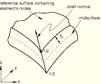
You can define the distance (measured as a fraction of the shell's thickness) from the shell's midsurface to the reference surface containing the element's nodes (see “Defining the initial geometry of conventional shell elements,” Section 23.6.3). Positive values of the offset are in the positive normal direction (see “Shell elements: overview,” Section 23.6.1). When the offset is set equal to 0.5, the top surface of the shell is the reference surface. When the offset is set equal to –0.5, the bottom surface is the reference surface. The default offset is 0, which indicates that the middle surface of the shell is the reference surface.
You can specify an offset value that is greater in magnitude than 0.5. However, this technique should be used with caution in regions of high curvature. All kinematic quantities, including the element's area, are calculated relative to the reference surface, which may lead to a surface area integration error, affecting the stiffness and mass of the shell.
An offset to the shell's top surface is illustrated in Figure 23.6.6–1.
A shell offset value can be specified only if a material definition is referenced or a composite shell section is defined and is ignored when the section definition is applied to continuum shell elements.
You can define offsets for homogeneous conventional shells on an element-by-element basis with an element property assignment. See “Assigning element properties on an element-by-element basis,” Section 21.1.5, for details.
| Input File Usage: | Use the following option to specify a value for the shell offset: |
*SHELL GENERAL SECTION, OFFSET=offset The OFFSET parameter accepts a value or a label (SPOS or SNEG). Specifying SPOS is equivalent to specifying a value of 0.5; specifying SNEG is equivalent to specifying a value of –0.5. |
| ABAQUS/CAE Usage: | Property module: Assign |
You can define a conventional shell with continuously varying thickness by specifying the thickness of the shell at the nodes. This method can be used only if the section is defined in terms of material properties; it cannot be used if the section behavior is defined by specifying the equivalent section properties directly. For continuum shell elements a continuously varying thickness can be defined through the element nodal geometry; hence, the nodal thickness is not meaningful.
If you indicate that the nodal thicknesses will be specified, for homogeneous shells any constant shell thickness you specify will be ignored, and the shell thickness will be interpolated from the nodes. The thickness must be defined at all nodes connected to the element.
For composite shells the total thickness is interpolated from the nodes, and the constant layer thicknesses you specify are scaled proportionally such that the sum of the layer thicknesses is equal to the total thickness.
You can define thicknesses for homogeneous conventional shells on an element-by-element basis with an element property assignment. See “Assigning element properties on an element-by-element basis,” Section 21.1.5, for details.
| Input File Usage: | Use both of the following options: |
*NODAL THICKNESS *SHELL GENERAL SECTION, NODAL THICKNESS |
| ABAQUS/CAE Usage: | Continuously varying shell thicknesses are not supported in ABAQUS/CAE. |
In the finite-membrane-strain shell elements in ABAQUS/Standard and in all shell elements in ABAQUS/Explicit (see “Choosing a shell element,” Section 23.6.2) ABAQUS allows for a possible uniform change in the shell thickness based either on the element material definition or on a specified effective section Poisson's ratio. Thickness change is considered only in geometrically nonlinear analysis (see “General and linear perturbation procedures,” Section 6.1.2).
For conventional shell elements you can specify a value for the effective Poisson's ratio for the section to cause a thickness direction strain under plane stress conditions to be a linear function of the membrane strains. This value must be between –1.0 and 0.5. A value of 0.5 will enforce incompressible behavior of the element in response to membrane strain; a value of 0.0 will enforce constant shell thickness; and a negative value will result in an increase in the shell thickness in response to tensile membrane strains. The default value is 0.5.
When the equivalent section properties are specified directly, the section stiffnesses are scaled during deformation to account for changes in the shell thickness. Specify an effective Poisson's ratio of 0.0 if no scaling of the section stiffnesses is desired.
Alternatively, you can cause the shell thickness to change based on the initial elastic properties of the material definition if these properties are available during the preprocessing stage of input. For example, when the material behavior is defined by user subroutine UMAT or VUMAT or when the section is defined by user subroutine UGENS in ABAQUS/Standard, ABAQUS cannot compute an effective Poisson's ratio.
| Input File Usage: | Use the following option to specify a value for the effective Poisson's ratio: |
*SHELL GENERAL SECTION, POISSON= Use the following option to cause the shell thickness to change based on the initial elastic properties of the material: *SHELL GENERAL SECTION, POISSON=ELASTIC |
| ABAQUS/CAE Usage: | Property module: Create Section: select Shell as the section Category and Homogeneous or Composite as the section Type: Section integration: Before analysis: Advanced: Section Poisson's ratio: Use analysis default or Specify value: |
You cannot specify a shell thickness direction behavior based on the initial elastic material definition in ABAQUS/CAE. |
For continuum shell elements the thickness direction strain is computed from the element nodal displacements, which in turn depend on the effective thickness modulus and the section Poisson's ratio. Specifying a section Poisson's ratio causes a thickness direction strain under plane stress conditions to be a linear function of the membrane strains. The stress in the thickness direction is computed from the effective thickness modulus and the effective strain in the thickness direction (thickness direction strain computed from the nodal displacements minus the thickness direction strain under plane stress conditions due to membrane effects). The stress in the thickness direction is computed at the element center and is assumed to be constant through the thickness.
You can choose to precalculate an effective thickness modulus and section Poisson's ratio based on the initial elastic material properties, as defined by the initial temperatures and predefined field variables evaluated at the midpoint of each material layer. Alternatively, you can specify the effective thickness modulus and section Poisson's ratio directly to define the thickness elasticity assuming a homogeneous section. The latter method must be used to define the thickness response if the material properties are unavailable during the preprocessing stage of input; for example, when the material behavior is defined by user subroutine UMAT or VUMAT or when the section is defined by user subroutine UGENS in ABAQUS/Standard. By default, the section Poisson's ratio is 0.5 and the effective thickness modulus is twice the initial in-plane shear modulus based on the material definition.
| Input File Usage: | Use the following option to define an effective thickness modulus directly: |
*SHELL GENERAL SECTION, THICKNESS MODULUS= Use the following option to specify a value for the effective Poisson's ratio: *SHELL GENERAL SECTION, POISSON= Use the following option to cause the shell thickness to change based on the element elastic material definition: *SHELL GENERAL SECTION, POISSON=ELASTIC |
| ABAQUS/CAE Usage: | Property module: Create Section: select Shell as the section Category and Homogeneous or Composite as the section Type: Section integration: Before analysis: Advanced: Section Poisson's ratio: Use analysis default to base the thickness properties on the element material definition or Specify value: |
You cannot specify a shell thickness direction behavior based on the initial elastic material definition in ABAQUS/CAE. |
You can provide nondefault values of the transverse shear stiffness. You must specify the transverse shear stiffness for shear flexible shells in ABAQUS/Standard if the section properties are specified in user subroutine UGENS. If you do not specify the transverse shear stiffness, it will be calculated as described in “Shell section behavior,” Section 23.6.4.
| Input File Usage: | Use both of the following options: |
*SHELL GENERAL SECTION *TRANSVERSE SHEAR STIFFNESS |
| ABAQUS/CAE Usage: | Property module: Create Section: select Shell as the section Category and Homogeneous or Composite as the section Type: Section integration: Before analysis: Advanced: toggle on Specify transverse shear |
You can define initial stresses (see “Defining initial stresses” in “Initial conditions,” Section 27.2.1) for general shell sections that will be applied as initial section forces and moments. Initial conditions can be specified only for the membrane forces, the bending moments, and the twisting moment. Initial conditions cannot be prescribed for the transverse shear forces.
In ABAQUS/Explicit you can specify second-order accuracy in the shell element formulation. See “Section controls,” Section 21.1.4, for more information.
| Input File Usage: | *SHELL GENERAL SECTION, CONTROLS=name |
| ABAQUS/CAE Usage: | Mesh module: Mesh |
You can specify a nondefault hourglass control formulation or scale factors for elements that use reduced integration. See “Section controls,” Section 21.1.4, for more information.
In ABAQUS/Standard the nondefault enhanced hourglass control formulation is available only for S4R and SC8R elements.
In ABAQUS/Standard you can modify the default values for hourglass control stiffness based on the default total stiffness approach for elements that use hourglass control and define a scaling factor for the stiffness associated with the drill degree of freedom (rotation about the surface normal) for elements that use six degrees of freedom at a node.
No default values are available for hourglass control stiffness if the section properties are specified in user subroutine UGENS. Therefore, you must specify the hourglass control stiffness when UGENS is used to specify the section properties for reduced-integration elements.
The stiffness associated with the drill degree of freedom is the average of the direct components of the transverse shear stiffness multiplied by a scaling factor. In most cases the default scaling factor is appropriate for constraining the drill rotation to follow the in-plane rotation of the element. If an additional scaling factor is defined, the additional scaling factor should not increase or decrease the drill stiffness by more than a factor of 100.0 for most typical applications. Usually, a scaling factor between 0.1 and 10.0 is appropriate.
There are no hourglass stiffness factors or scale factors for hourglass stiffness for the nondefault enhanced hourglass control formulation. You can define the scale factor for the drill stiffness for the nondefault enhanced hourglass control formulation.
| Input File Usage: | Use both of the following options to specify a nondefault hourglass control formulation or scale factors for reduced-integration elements: |
*SECTION CONTROLS, NAME=name
*SHELL GENERAL SECTION, CONTROLS=name
Use both of the following options in ABAQUS/Standard to modify the default values for hourglass control stiffness based on the default total stiffness approach for reduced-integration elements and to define a scaling factor for the stiffness associated with the drill degree of freedom (rotation about the surface normal) for six degree of freedom elements: *SHELL GENERAL SECTION *HOURGLASS STIFFNESS |
| ABAQUS/CAE Usage: | Mesh module: Mesh |
You can define the mass per unit area for conventional shell elements whose section properties are specified directly in terms of the section stiffness (either directly in the section definition or, in ABAQUS/Standard, in user subroutine UGENS). The density is required, for example, in a dynamic analysis or for gravity loading. See “Density,” Section 16.2.1, for details.
The density is defined as part of the material definition for shells whose section properties include a material definition.
| Input File Usage: | Use either of the following options: |
*SHELL GENERAL SECTION, ELSET=name, DENSITY= |
| ABAQUS/CAE Usage: | You cannot define the shell section properties directly or in user subroutine UGENS in ABAQUS/CAE. |
You can include mass and stiffness proportional damping in a shell section definition. See “Material damping,” Section 20.1.1, for more information about material damping in ABAQUS.
| Input File Usage: | Use the following option immediately after the *SHELL GENERAL SECTION option: |
*DAMPING |
| ABAQUS/CAE Usage: | Property module:
Create Section: select Shell as the section Category and Homogeneous or
Composite as the section Type: Section integration: Before analysis:
Basic: Material: name
Material editor: Name: name: Mechanical |
Temperatures and field variables can be specified by defining the value at the reference surface of the shell or by defining the values at the nodes of a continuum shell element. The actual values of the temperatures and field variables are specified as either predefined fields or initial conditions (see “Predefined fields,” Section 27.6.1, or “Initial conditions,” Section 27.2.1).
The following output variables are available from ABAQUS/Explicit as element output: section forces and moments, section strains, element energies, element stable time increment, and element mass scaling factor.
The output that is available from ABAQUS/Standard depends on how the section behavior is defined.
Output if the section is defined in terms of material properties
For shells whose section properties include a material definition (homogeneous or composite), section forces and moments and section strains are available as element output. The section moments are calculated relative to the reference surface. In addition, stress (in-plane and, for certain elements, transverse shear), strain, and orthotropic failure measures can be output. Since the behavior of the material is linear, three section points per layer (the bottom, middle, and top, respectively) are available for output. Stress invariants and principal stresses are not available as output but can be visualized in ABAQUS/CAE.
Output if the equivalent section properties are specified directly or in UGENS
If the ![]() matrix is used to specify the equivalent section properties directly or if user subroutine UGENS is used, section point stresses and strains and section strains are not available for output or visualization in ABAQUS/CAE; only section forces and moments can be requested for output or visualized in ABAQUS/CAE.
matrix is used to specify the equivalent section properties directly or if user subroutine UGENS is used, section point stresses and strains and section strains are not available for output or visualization in ABAQUS/CAE; only section forces and moments can be requested for output or visualized in ABAQUS/CAE.