Products: ABAQUS/Standard ABAQUS/Explicit ABAQUS/CAE
The ABAQUS/Standard shell element library includes:
elements for three-dimensional shell geometries;
elements for axisymmetric geometries with axisymmetric deformation;
elements for axisymmetric geometries with general deformation that is symmetric about one plane;
elements for stress/displacement, heat transfer, and fully coupled temperature-displacement analysis;
general-purpose elements, as well as elements specifically suitable for the analysis of “thick” or “thin” shells;
general-purpose, three-dimensional, first-order elements that use reduced or full integration;
elements that account for finite membrane strain;
elements that use five degrees of freedom per node where possible, as well as elements that always use six degrees of freedom per node; and
continuum shell elements.
general-purpose three-dimensional elements to model “thick” or “thin” shells that account for finite membrane strains;
small-strain elements;
an element for axisymmetric geometries with axisymmetric deformation; and
continuum shell elements.
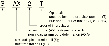
The naming convention for shell elements depends on the element dimensionality.
Three-dimensional shell elements in ABAQUS are named as follows:
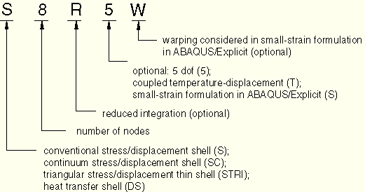
The conventional stress/displacement shell elements in ABAQUS can be used in three-dimensional or axisymmetric analysis. In ABAQUS/Standard they use linear or quadratic interpolation and allow mechanical and/or thermal (uncoupled) loading; in ABAQUS/Explicit they use linear interpolation and allow mechanical loading. These elements can be used in static or dynamic procedures. Some elements include the effect of transverse shear deformation and thickness change, while others do not. Some elements allow large rotations and finite membrane deformation, while others allow large rotations but small strains.
The value of temperatures at the integration locations in the surface of the shell used to compute the thermal stresses depends on whether first-order or second-order elements are used. An average temperature is used at the integration location in linear elements so that the thermal strain is constant throughout the shell surface. A linearly varying temperature distribution is used in higher-order shell elements. Field variables in stress/displacement shell elements are interpolated the same way as temperatures.
The stress/displacement continuum shell elements in ABAQUS can be used in three-dimensional analysis. Continuum shells discretize an entire three-dimensional body, unlike conventional shells which discretize a reference surface (see “Shell elements: overview,” Section 23.6.1). These elements have displacement degrees of freedom only, use linear interpolation, and allow mechanical and/or thermal (uncoupled) loading for static and dynamic procedures. The continuum shell elements are general-purpose shells that allow finite membrane deformation and large rotations and, thus, are suitable for nonlinear geometric analysis. These elements include the effects of transverse shear deformation and thickness change.
Continuum shell elements employ first-order layer-wise composite theory. Unlike conventional shells, continuum shell elements can be stacked to provide more refined through-thickness response. Stacking continuum shell elements allows for a richer transverse shear stress and force prediction and allows for the prediction of through-thickness pinching force. Care should be taken when stacking a small number of continuum shell elements, because the convergence may not be monotonic (see “Performance of continuum and shell elements for linear analysis of bending problems,” Section 2.3.5 of the ABAQUS Benchmarks Manual). Furthermore, the thickness strain mode may yield a small stable time increment for thin continuum shell elements in ABAQUS/Explicit (see “Shell section behavior,” Section 23.6.4).
Continuum shell elements are more accurate in contact modeling than conventional shells, since they employ two-sided contact taking into account changes in thickness no matter how thick the elements are compared to other element dimensions.
These elements, available only in ABAQUS/Standard and only with conventional shell element geometry, are intended to model heat transfer in shell-type structures. They provide the values of temperature at a number of points through the thickness at each shell node. This output can be input directly to the equivalent stress analysis shell element for sequentially coupled thermal-stress analysis (“Sequentially coupled thermal-stress analysis,” Section 6.5.3).
The temperature variation is assumed to be piecewise quadratic through the thickness, while the interpolation on the reference surface of the shell is the same as that of the corresponding stress elements. For shell sections integrated during the analysis (“Using a shell section integrated during the analysis to define the section behavior,” Section 23.6.5) you can specify the number of section points used for cross-section integration and thickness-direction temperature interpolation at each node. Only Simpson's rule can be used for integration through the shell thickness.
The temperature on the bottom surface of the shell (the surface in the negative direction along the shell normal—see “Defining the initial geometry of conventional shell elements,” Section 23.6.3) is degree of freedom 11. The temperature on the top surface is degree of freedom ![]() . A maximum of 20 temperature degrees of freedom can exist at a node. For a single-layer shell
. A maximum of 20 temperature degrees of freedom can exist at a node. For a single-layer shell ![]() is the total number of integration points used through the shell section. If a single section point is used for the cross-section integration, there is no temperature variation through the thickness of the shell and the temperature of the entire shell cross-section is degree of freedom 11. For a multi-layered shell the temperature at the top of each layer is the same as the temperature at the bottom of the next layer. Therefore,
is the total number of integration points used through the shell section. If a single section point is used for the cross-section integration, there is no temperature variation through the thickness of the shell and the temperature of the entire shell cross-section is degree of freedom 11. For a multi-layered shell the temperature at the top of each layer is the same as the temperature at the bottom of the next layer. Therefore,
To use the temperatures that are saved in the ABAQUS/Standard results file directly as input to a thermal-stress analysis, the mesh and the specification of the number of temperature points in the shell sections must be the same in the heat transfer and the stress analysis models. In addition, multi-layered heat transfer shell elements must have the same number of integration points in each layer.
The coupled temperature-displacement shell elements available in ABAQUS/Standard have conventional shell element geometry and use quadratic interpolation for the geometry and displacements. The temperature is interpolated linearly from the corner or end nodes; the lower-order temperature interpolation is chosen to give the same interpolation order for thermal strain, which is proportional to temperature, as for total strain. All terms in the governing equations are integrated in the reference surface of the shell using a conventional Gauss scheme; Simpson's rule is used to integrate through the shell thickness.
The temperature variation through the shell thickness is assumed to be piecewise quadratic and is interpolated from temperatures at a series of points through the thickness of the shell at each node. The number of temperature values to be used at each node is determined by the number of integration points that you specify in the shell section definition (see “Defining the shell section integration” in “Using a shell section integrated during the analysis to define the section behavior,” Section 23.6.5). Temperature values are stored as degrees of freedom 11, 12, 13, etc. in a manner that is identical to that used for heat transfer shell elements.
ABAQUS includes general-purpose, conventional shell elements as well as conventional shell elements that are valid for thick and thin shell problems. See below for a discussion of what constitutes a “thick” or “thin” shell problem. This concept is relevant only for elements with displacement degrees of freedom.
The general-purpose, conventional shell elements provide robust and accurate solutions to most applications and will be used for most applications. However, in certain cases, for specific applications in ABAQUS/Standard, enhanced performance may be obtained with the thin or thick conventional shell elements; for example, if only small strains occur and five degrees of freedom per node are desired.
The continuum shell elements can be used for any thickness; however, thin continuum shell elements may result in a small stable time increment in ABAQUS/Explicit.
These elements allow transverse shear deformation. They use thick shell theory as the shell thickness increases and become discrete Kirchhoff thin shell elements as the thickness decreases; the transverse shear deformation becomes very small as the shell thickness decreases.
Element types S3/S3R, S3RS, S4, S4R, S4RS, S4RSW, SAX1, SAX2, SAX2T, SC6R, and SC8R are general-purpose shells.
In ABAQUS/Standard thick shells are needed in cases where transverse shear flexibility is important and second-order interpolation is desired. When a shell is made of the same material throughout its thickness, this occurs when the thickness is more than about 1/15 of a characteristic length on the surface of the shell, such as the distance between supports for a static case or the wavelength of a significant natural mode in dynamic analysis.
ABAQUS/Standard provides element types S8R and S8RT for use only in thick shell problems.
In ABAQUS/Standard thin shells are needed in cases where transverse shear flexibility is negligible and the Kirchhoff constraint must be satisfied accurately (i.e., the shell normal remains orthogonal to the shell reference surface). For homogeneous shells this occurs when the thickness is less than about 1/15 of a characteristic length on the surface of the shell, such as the distance between supports or the wave length of a significant eigenmode. However, the thickness may be larger than 1/15 of the element length.
ABAQUS/Standard has two types of thin shell elements: those that solve thin shell theory (the Kirchhoff constraint is satisfied analytically) and those that converge to thin shell theory as the thickness decreases (the Kirchhoff constraint is satisfied numerically).
The element that solves thin shell theory is STRI3. STRI3 has six degrees of freedom at the nodes and is a flat, faceted element (initial curvature is ignored). If STRI3 is used to model a thick shell problem, the element will always predict a thin shell solution.
The elements that impose the Kirchhoff constraint numerically are S4R5, STRI65, S8R5, S9R5, SAXA1n, and SAXA2n. These elements should not be used for applications in which transverse shear deformation is important. If these elements are used to model a thick shell problem, the elements may predict inaccurate results.
ABAQUS has both finite-strain and small-strain shell elements. This concept is relevant only for elements with displacement degrees of freedom.
Element types S3/S3R, S4, S4R, SAX1, SAX2, SAX2T, SAXA1n, and SAXA2n account for finite membrane strains and arbitrarily large rotations; therefore, they are suitable for large-strain analysis. The underlying formulation is described in “Axisymmetric shell elements,” Section 3.6.2 of the ABAQUS Theory Manual; “Finite-strain shell element formulation,” Section 3.6.5 of the ABAQUS Theory Manual; and “Axisymmetric shell element allowing asymmetric loading,” Section 3.6.7 of the ABAQUS Theory Manual.
Continuum shell elements SC6R and SC8R account for finite membrane strains, arbitrary large rotation, and allow for changes in thickness, making them suitable for large-strain analysis. Computation of the change in thickness is based on the element nodal displacements, which in turn are computed from an effective elastic modulus defined at the beginning of an analysis.
In ABAQUS/Standard the three-dimensional “thick” and “thin” element types STRI3, S4R5, STRI65, S8R, S8RT, S8R5, and S9R5 provide for arbitrarily large rotations but only small strains. The change in thickness with deformation is ignored in these elements.
In ABAQUS/Explicit element types S3RS, S4RS, and S4RSW are provided for shell problems with small membrane strains and arbitrarily large rotations. Many impact dynamics analyses fall within this class of problems, including those of shell structures undergoing large-scale buckling behavior but relatively small amounts of membrane stretching and compression. Although solution accuracy may degrade as membrane strains become large, the small-strain shell elements in ABAQUS/Explicit provide a computationally efficient alternative to the finite-membrane-strain elements for appropriate applications. The underlying formulation is described in “Small-strain shell elements in ABAQUS/Explicit,” Section 3.6.6 of the ABAQUS Theory Manual.
For conventional shell elements in ABAQUS/Standard you must specify a section Poisson's ratio as part of the shell section definition to allow for the shell thickness in finite-strain elements to change as a function of the membrane strain. If the section Poisson's ratio is defined as zero, the shell thickness will remain constant and the elements are, therefore, suited for small-strain, large-rotation analysis. For typical large-strain applications with metals (such as sheet metal forming analysis) or rubber, the section Poisson's ratio should be set to 0.5 (the default value) to reproduce the incompressible response of the material at large plastic or hyperelastic deformation. The change in thickness is ignored for the small-strain shell elements in ABAQUS/Standard.
For finite-strain or small-strain conventional shell elements in ABAQUS/Explicit defined by integrating the section during the analysis, the change in thickness is calculated by enforcing the plane stress condition and using either the material definition, where the thickness-direction strain is integrated through the shell thickness, or the membrane section strains along with a specified effective section Poisson's ratio. For finite-strain or small-strain conventional shell elements defined by general shell sections, the change in thickness is determined from the membrane section strains by enforcing the plane stress condition and using a specified effective section Poisson's ratio.
For continuum shells in ABAQUS/Standard and ABAQUS/Explicit the change in thickness is calculated from the nodal displacements, an effective thickness modulus, and an effective section Poisson's ratio. ABAQUS computes an effective thickness strain based on the total thickness change and a strain obtained by enforcing the plane stress condition for a section Poisson's ratio. By default, the thickness modulus and section Poisson's ratio are based on the initial material properties, as defined by the initial temperatures and predefined field variables evaluated at the midpoint of each material layer. Alternatively, you can define an effective thickness modulus and effective section Poisson's ratio for the shell section. The thickness direction stiffness remains constant and is not recalculated during the analysis.
See “Defining a change in shell thickness due to straining” in “Using a shell section integrated during the analysis to define the section behavior,” Section 23.6.5, and “Defining a change in shell thickness due to straining” in “Using a general shell section to define the section behavior,” Section 23.6.6, for details.
Two types of three-dimensional conventional shell elements are provided in ABAQUS/Standard: ones that use five degrees of freedom (three displacement components and two in-surface rotation components) where possible and ones that use six degrees of freedom (three displacement components and three rotation components) at all nodes.
The elements that use five degrees of freedom (S4R5, STRI65, S8R5, S9R5) can be more economical. However, they are available only as “thin” shells (they cannot be used as “thick” shells) and cannot be used for finite-strain applications (although they model large rotations with small strains accurately). In addition, output for the five degree of freedom shell elements is restricted as follows:
At nodes that use the two in-surface rotation components, the values of these in-surface rotations are not available for output.
When output variable NFORC is requested, moments corresponding to the in-surface rotations are not available for output.
has kinematic boundary conditions applied to rotational degrees of freedom,
is used in a multi-point constraint (“General multi-point constraints,” Section 28.2.2) that involves rotational degrees of freedom,
is shared with a beam element or a shell element that uses the three global rotation components at all nodes,
is on a fold line in the shell (that is, on a line where shells with different surface normals come together), or
is loaded with moments.
Many shell element types in ABAQUS use reduced (lower-order) integration to form the element stiffness. The mass matrix and distributed loadings are still integrated exactly. Reduced integration usually provides more accurate results (provided the elements are not distorted or loaded in in-plane bending) and significantly reduces running time, especially in three dimensions.
When reduced integration is used with first-order (linear) elements, hourglass control is required. Therefore, when using first-order reduced-integration elements, you must check if hourglassing is occurring; if it is, a finer mesh may be required or concentrated loads must be distributed over multiple nodes. The second-order reduced-integration elements available in ABAQUS/Standard generally do not have the same difficulty and are recommended in cases when the solution is expected to be smooth. First-order elements are recommended when large strains or very high strain gradients are expected.
In ABAQUS/Standard you can specify nondefault hourglass control parameters for shell elements. In ABAQUS/Explicit you can specify second-order accuracy in the element formulation or nondefault hourglass control parameters for S4R, S4RS, and S4RSW elements. See “Section controls,” Section 21.1.4, for more information.
| Input File Usage: | Use the following options in ABAQUS/Standard: |
*SHELL SECTION or *SHELL GENERAL SECTION
*HOURGLASS STIFFNESS
Use one of the following options in ABAQUS/Explicit: *SHELL SECTION, CONTROLS=name *SHELL GENERAL SECTION, CONTROLS=name |
| ABAQUS/CAE Usage: | Mesh module: Mesh |
A number of modeling issues must be considered when using shell elements.
Both S3 and S3R refer to the same 3-node triangular shell element. This element is a degenerated version of S4R that is fully compatible with S4R and, in ABAQUS/Standard, S4.
Element S3RS, available in ABAQUS/Explicit, is a degenerated version of S4RS that is fully compatible with S4RS.
S3/S3R and S3RS provide accurate results in most loading situations. However, because of their constant bending and membrane strain approximations, high mesh refinement may be required to capture pure bending deformations or solutions to problems involving high strain gradients.
Element types S4, S4R, S4R5, S4RS, S8R5, and S9R5 can be degenerated to triangles. However, for elements S4 (element S4 degenerated to a triangle may exhibit overly stiff response in membrane deformation), S4R, and S4RS it is recommended that S3R and S3RS be used instead.
The quarter-point technique (moving the midside nodes to the quarter points to give a ![]() singularity for elastic fracture mechanics applications) can be used with the quadratic element types S8R5 and S9R5 (see “Element definition,” Section 2.2.1). The accuracy of the element is very significantly reduced when it is degenerated to a triangle; therefore, this is not recommended except for special applications, such as fracture.
singularity for elastic fracture mechanics applications) can be used with the quadratic element types S8R5 and S9R5 (see “Element definition,” Section 2.2.1). The accuracy of the element is very significantly reduced when it is degenerated to a triangle; therefore, this is not recommended except for special applications, such as fracture.
Element types S8R and S8RT cannot be degenerated to triangles. Element types DS4 and DS8 can be degenerated to triangles, but it is recommended that DS3 and DS6 elements be used instead.
Continuum shell elements are similar to continuum solids from a modeling point of view. The element geometries for the SC6R and SC8R elements are a triangular prism and hexahedron, respectively, with displacement degrees of freedom only.
Continuum shell elements must be oriented correctly, since these elements have a thickness direction associated with them. See “Shell elements: overview,” Section 23.6.1, for further details on element connectivity and orientation.
When classical shell structures (structures in which only the midsurface geometry and kinematic constraints are provided) are analyzed, care must be taken that appropriate moments and rotations are specified. For example, a moment may be applied as a force-couple system at the corresponding nodes on the top and bottom faces. A rotation boundary condition may be specified through a kinematic constraint to yield the appropriate displacement boundary conditions on the edge of the continuum shell.
Continuum shell elements can be connected directly to first-order continuum solids without any kinematic transition. An appropriate kinematic transition needs to be provided when conventional shell elements are connected to continuum shell elements to correctly transfer the moment/rotation at the reference surface of a conventional shell. Such a transition can be defined with a shell-to-solid coupling constraint or any other kinematic constraint, such as a surface-based coupling constraint, a multi-point constraint, or a linear constraint equation.
The SC6R element is a degenerated version of the SC8R element. The SC6R element provides accurate results in most loading situations. However, because of its constant bending and membrane strain approximations, high mesh refinement may be required to capture pure bending deformations or solutions to problems involving high strain gradients.
Continuum shell elements, SC6R and SC8R, allow two-sided contact with changes in the thickness and are thus suitable for modeling contact.
In ABAQUS/Explicit the element stable time increment can be controlled by the continuum shell element thickness, particularly for thin shell applications. This may increase significantly the number of increments taken to complete the analysis when compared to the same problem modeled with conventional shell elements. The small stable time increment size may be mitigated by specifying a lower stiffness in the thickness direction when appropriate.
Continuum shell elements cannot be used with the hyperelastic or hyperfoam material definitions, nor can they be used with general shell sections where the section stiffness is provided directly.
Although continuum shells provide robust and accurate solutions to most shell applications, these elements may show slow convergence for very thin shell applications. In such cases conventional thin shell elements should be used.
For a “sandwich” shell, in which parts of the cross-section are made of a softer material (especially when the layers are nonisotropic so that some layers are weak in particular directions), the transverse shear flexibility can be important even when the shell is rather thin. Use of general-purpose shell elements or stacking continuum shell elements is recommended in such cases. See “Shell section behavior,” Section 23.6.4, for a discussion of transverse shear stiffness in shell elements.
In ABAQUS/Standard curved elements (STRI65, S8R5, S9R5) are preferable for modeling bending of a thin curved shell.
Element type STRI3 is a flat facet element. If this element is used to model bending of a curved shell, a dense mesh may be required to obtain accurate results.
Element type S8R5 may give inaccurate results for buckling problems of doubly curved shells due to the fact that the internally defined center node may not be positioned on the actual shell surface. Element type S9R5 should be used instead.
Element type S8R5 is converted automatically to element type S9R5 if a slave surface in a contact pair is attached to the element.
Element type S4 is a fully integrated, general-purpose, finite-membrane-strain shell element available in ABAQUS/Standard. The element's membrane response is treated with an assumed strain formulation that gives accurate solutions to in-plane bending problems, is not sensitive to element distortion, and avoids parasitic locking.
Element type S4 does not have hourglass modes in either the membrane or bending response of the element; hence, the element does not require hourglass control. The element has four integration locations per element compared with one integration location for S4R, which makes the element computationally more expensive. S4 is compatible with both S4R and S3R. S4 can be used for problems prone to membrane- or bending-mode hourglassing, in areas where greater solution accuracy is required, or for problems where in-plane bending is expected. In all of these situations S4 will outperform element type S4R. S4 cannot be used with the hyperelastic or hyperfoam material definitions.