Product: ABAQUS/Standard
The following element properties can be modified on an element-by-element basis from the values assigned by a section definition:
thicknesses, offsets, section stiffness matrices, and orientations for single-layer shell elements; and
orientations for non-composite continuum elements.
Finite element analyses require the modeling of spatially varying element properties. Element properties include geometric information, such as shell thickness, and modeling information, such as material orientation.
Element section definitions are the primary means of assigning element properties in an ABAQUS model (for example, see “Solid (continuum) elements,” Section 22.1.1; “Using a shell section integrated during the analysis to define the section behavior,” Section 23.6.5; or “Using a general shell section to define the section behavior,” Section 23.6.6). The element section definitions allow concise element property assignments when the majority of the elements in a model can be grouped into a relatively small number of element sets that share identical element properties; elements of the same type (e.g., continuum, shell, beam, etc.) can be included in the same element section definition if they share common element properties.
In some applications there may be very little element property variation in a model. For example, a model of a soda can may contain thousands of shell elements; but if the shell thickness and constitutive behavior are uniform throughout the model, the element properties can be assigned with a single shell section definition. However, in other applications the element properties may vary significantly. It is not uncommon for aerospace and marine applications to have thousands of different thicknesses, offsets, and material orientations for the shell elements in the model. In such cases creating separate section definitions and element sets to accommodate the different element properties may be inconvenient. An alternative approach, which can be used in certain situations described below, is to use the section definitions to define default element properties and to redefine, as needed, specific element properties on selected elements using element property assignments.
To redefine specific element properties with an element property assignment, you must specify an element property label, which is a self-describing identifier of the element property that is to be modified. Supported element property labels are discussed below. In addition, you must specify the name of the distribution (see “Distribution definition,” Section 2.7.1) that identifies the elements in the model for which the specified property will be modified as well as the data used to modify it. Only distributions defined on elements can used in an element property assignment.
The ability to redefine element properties with an element property assignment does not eliminate the need for an element section definition. Each element in an ABAQUS model must have a valid section definition.
In general, it is recommended that you only use element property assignments in cases where doing so will significantly reduce the number of required section definitions. For example, suppose a large shell model (with tens of thousands of shell elements) needed multiple section definitions to handle different shell offsets. If the offsets can be handled by a few section definitions, it is generally more efficient to do so. However, if hundreds or thousands of different section definitions are required, it is generally more efficient to use as few section definitions as possible and define the shell offsets with an element property assignment.
An element property assignment does not have to be applied to all elements associated with a given section definition. See “Example 1: A simple case of redefining a shell offset with an element property assignment” below.
When element property assignments are used in a model, it is most efficient to use one distribution definition for each element property. An element property assignment can span multiple section definitions. See “Example 5: Element property assignments that span section definitions” below. There is no benefit in defining multiple distribution definitions for a given element property label. For example, suppose a given model has 1000 shell elements, and the thickness for each shell element is redefined with an element property assignment. In this case one distribution definition and element property assignment for thickness should be used. ABAQUS will not prevent you from defining and using multiple distributions for the thickness; however, if many separate distributions are used, performance during input file preprocessing may be noticeably slower compared to the case with a single distribution.
If any element in a model has one or more element properties defined by an element property assignment, that model cannot be used in an ABAQUS/Standard analysis that uses symmetric model generation (“Symmetric model generation,” Section 10.3.1).
If any element in a model has one or more element properties defined by an element property assignment, that model cannot be used in an import analysis that involves ABAQUS/Explicit. Element property assignments are supported only for import from one ABAQUS/Standard analysis to another. See “Transferring results from one ABAQUS/Standard analysis to another,” Section 9.2.3.
| Input File Usage: | *ELEMENT PROPERTIES element property label, distribution name |
The element property labels are single word labels, which must be entered exactly as shown in Table 21.1.5–1, Table 21.1.5–2, and Table 21.1.5–3; otherwise, an error will occur during input file preprocessing. The *ELEMENT PROPERTIES option can appear anywhere in the assembly- or model-level of an ABAQUS/Standard model (see “Defining an assembly,” Section 2.9.1). It is not a suboption of any other ABAQUS/Standard option. However, for clarity it is often useful to have the *ELEMENT PROPERTIES option near the associated distribution definitions. There is no limit on the number of *ELEMENT PROPERTIES options that can appear in an input file. |
Table 21.1.5–1 Supported element property labels for single-layer shell elements defined using cross-section definitions that require numerical integration.
| Element property label | Description | Required algebraic data type for distribution |
|---|---|---|
| OFFSET | Shell offset | SCALAR |
| ORIENTATION | Material orientation | ORIENTATION |
| THICKNESS | Shell thickness | SCALAR |
Table 21.1.5–2 Supported element property labels for single-layer shell elements defined using general cross-sections.
| Element property label | Description | Required algebraic data type for distribution |
|---|---|---|
| OFFSET | Shell offset | SCALAR |
| ORIENTATION | Material orientation | ORIENTATION |
| THICKNESS | Shell thickness | SCALAR |
| SHELL3DSTIFFNESS | General shell section stiffness (21 scalar values) | SHELL3D STIFFNESS |
Only selected element properties on shell and continuum elements can be redefined by an element property assignment. In addition, as discussed below, an element's section definition puts some restrictions on what element properties can be modified with an element property assignment.
Table 21.1.5–1 and Table 21.1.5–2 list the supported element properties for shell elements defined using shell cross-section definitions that require numerical integration (“Using a shell section integrated during the analysis to define the section behavior,” Section 23.6.5) and shell elements defined using general shell cross-section definitions (“Using a general shell section to define the section behavior,” Section 23.6.6), respectively. Shell element properties can be redefined only for single-layer shells, not composite shells. Table 21.1.5–3 lists the supported element properties (currently only material orientations) for continuum elements (“Solid (continuum) elements,” Section 22.1.1). Continuum element properties can be redefined only for single-material solids, not composite solids.
The first and second columns in the tables list the element property labels and a brief description of the property labels, respectively. The third column lists the required algebraic data type of the distribution for each element property label (see “Distribution definition,” Section 2.7.1). Element properties require certain data types; for example, a shell thickness can be specified only with a scalar floating point number. Therefore, only a scalar distribution can be applied to modify shell thicknesses with an element property assignment. If a distribution whose algebraic data type is different from the ones listed in Table 21.1.5–1, Table 21.1.5–2, and Table 21.1.5–3 is used for a given element property label, ABAQUS/Standard will issue an error message during input file preprocessing.
When element properties are redefined with an element property assignment, the same restrictions apply as when the properties are defined with a section definition. For example, a shell thickness redefined by an element property assignment must be a positive value.
A thickness for a shell element defined by an element property assignment takes precedence over the thickness defined by the section definition, including nodal thicknesses. A thickness for a shell element defined by an element property assignment must be a positive scalar. See “Example 2: Defining thickness for shell elements” below for an illustration of shell thickness redefinition.
Redefining the shell element thickness via an element property assignment is meaningful only if defining thickness for the shell is meaningful in the first place, as discussed in “Using a shell section integrated during the analysis to define the section behavior,” Section 23.6.5, and “Using a general shell section to define the section behavior,” Section 23.6.6. Notable exceptions include continuum shells, in which case the thickness is defined by the nodal geometry, and general shell section definitions that define the section stiffness directly, in which case the specified thickness is ignored. In addition, the thickness of a line spring element (see “Line spring elements for modeling part-through cracks in shells,” Section 26.10.1) cannot be modified with an element property assignment.
An offset for a shell element defined by an element property assignment takes precedence over the offset defined by the section definition. The offset can be set equal to a value that is greater in magnitude than 0.5. However, this option should be used with caution in regions of high curvature. All kinematic quantities, including the element's area, are calculated relative to the reference surface, which may lead to a surface area integration error, affecting the stiffness and mass of the shell. An element property assignment can be used to redefine the offset for any type of shell element except a continuum shell, for which an offset has no meaning.
An offset is meaningful only if the section properties are defined in terms of material properties; an offset is ignored if a general shell section behavior is defined through user subroutine UGENS or by specifying the section stiffness directly.
A local rectangular material coordinate system for a shell element defined by an element property assignment takes precedence over the orientation defined by the section definition. A rectangular coordinate system defined by an element property assignment is subject to the same restrictions as a rectangular coordinate system defined by a section definition (see “Orientations,” Section 2.2.5). An element property assignment can be used to redefine the material orientation for any type of shell element except for axisymmetric shell elements, which do not support orientations. The 1- and 2-axes defined by an element property assignment define local directions 1 and 2 on the shell element, respectively. See “Example 3: Defining material orientations for shell elements” below.
If a shell's general section behavior is defined by specifying the equivalent section properties directly, a distribution can be used to redefine the section stiffness with an element property assignment. Only the general section stiffness can be redefined; the thermal expansion response is defined by the section definition. See “Example 6: Defining shell section stiffness” below.
An element property assignment can be used only to define the section stiffness for conventional three-dimensional shell elements.
If the shell's general section behavior is defined through material properties or through user subroutine UGENS, the section stiffness cannot be redefined with an element property assignment.
A local rectangular material coordinate system for a continuum element defined by an element property assignment takes precedence over the orientation defined by the section definition. A rectangular coordinate system defined with an element property assignment is subject to the same restrictions as a rectangular coordinate system defined by a section definition (see “Orientations,” Section 2.2.5).
If an orientation is defined by an element property assignment for at least one continuum element associated with a given section definition, all elements that refer to that section definition must have an orientation defined through either the section definition or an element property assignment. Otherwise, ABAQUS/Standard will issue an error message during input file preprocessing. This restriction does not apply to shell elements.
For purposes of clarity, it is recommended that a given element property for a given element be redefined a maximum of one time. If two or more distributions are applied to the same element property label on the same element, the last specified distribution is applied. See “Example 4: Applying multiple distributions to the same element properties on the same elements” below.
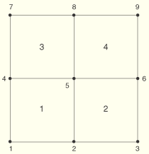
The following example illustrates a simple use case of redefining the offset of a shell element with an element property assignment. Consider the four-element shell model shown in Figure 21.1.5–1.
Suppose that all four shell elements have a thickness of 1.0, an offset of 0.1, and their constitutive behavior defined by a material named MAT1. In this case a single shell section definition could be used to assign these element properties (see “Using a shell section integrated during the analysis to define the section behavior,” Section 23.6.5), as shown below:... *ELSET, ELSET=SHELL 1, 2, 3, 4 *SHELL SECTION, ELSET=SHELL, MATERIAL=MAT1, OFFSET=0.1 1.0, *MATERIAL, NAME=MAT1 ...
Now consider the case where shell elements 1 and 2 have the same offset of 0.1, but elements 3 and 4 have offsets of 0.3 and 0.4, respectively. One approach is to partition the model with three separate section definitions to accommodate the different offsets:
...
*ELSET, ELSET=SHELL12
 1, 2
*ELSET, ELSET=SHELL3
 3,
*ELSET, ELSET=SHELL4
 4,
*SHELL SECTION, ELSET=SHELL12, MATERIAL=MAT1, OFFSET=0.1
 1.0,
*SHELL SECTION, ELSET=SHELL3, MATERIAL=MAT1, OFFSET=0.3
 1.0,
*SHELL SECTION, ELSET=SHELL4, MATERIAL=MAT1, OFFSET=0.4
 1.0,
...
Since elements 1 and 2 share common element properties (including their offsets), they are included in the same shell section definition.
An alternative approach is to use a single section definition and to redefine the offsets for elements 3 and 4 with an element property assignment as shown here:
...
*SHELL SECTION, ELSET=SHELL, MATERIAL=MAT1, OFFSET=0.1
 1.0,
*DISTRIBUTION, NAME=DIST1, LOCATION=ELEMENT, TYPE=SCALAR
 3,  0.3
 4,  0.4
*ELEMENT PROPERTIES
 OFFSET, DIST1
...
The first step in the above example is to assign a default offset value of 0.1 to elements 1 through 4. The second step is to define an element-based scalar distribution (in this case named DIST1) for elements 3 and 4. The final step is to redefine the offsets for elements 3 and 4 using an element property assignment in which the distribution DIST1 is used to modify the shell element offsets. Since only elements 3 and 4 are included in DIST1, the offsets for elements 1 and 2 remain unchanged from the default value specified in the shell section definition.
In the following example the shell thicknesses for the model in Figure 21.1.5–1 are defined using both nodal thicknesses and an element property assignment. A single section assignment is used for elements 1 through 4. The section definition uses nodal thickness assignments as the default thickness values. Elements 1 and 3 are assigned variable thicknesses (varying from 0.1 to 0.2). The thicknesses for elements 2 and 4 are redefined to a constant value of 0.1 by an element property assignment.
...
*NSET, NSET=NODE147
 1, 4, 7
*NSET, NSET=NODE258
 2, 5, 8
*NODAL THICKNESS
 NODE147, 0.1
 NODE258, 0.2
*ELSET, ELSET=SHELL14
 1, 2, 3, 4
*SHELL SECTION, ELSET=SHELL14, MATERIAL=MAT1, NODAL THICKNESS
 1.0,
*DISTRIBUTION, NAME=DIST_THICK, LOCATION=ELEMENT, TYPE=SCALAR
 2,  0.1
 4,  0.1
*ELEMENT PROPERTIES
 THICKNESS, DIST_THICK
...
In general, as discussed in “Using a shell section integrated during the analysis to define the section behavior,” Section 23.6.5, and “Using a general shell section to define the section behavior,” Section 23.6.6, if nodal thicknesses are used in a section definition, a nodal thickness must be assigned to each node connected to all elements in the associated element set (in this example element set SHELL14). In other words, if a nodal thickness was not assigned to nodes 1, 2, 4, 5, 7, or 8, an error would occur during input file preprocessing. However, since the thicknesses of elements 2 and 4 are redefined using an element property assignment, a nodal thickness does not have to be defined for nodes 3, 6, and 9 since they are not connected to an element that uses the nodal thickness. If a nodal thickness were assigned to these nodes, the values would be ignored.
In the following example a different material orientation is applied to each element in Figure 21.1.5–1. If only section definitions are used, a different section assignment would be needed for each shell element as shown here:
...
*ELSET, ELSET=SHELL1
 1,
*ELSET, ELSET=SHELL2
 2,
*ELSET, ELSET=SHELL3
 3,
*ELSET, ELSET=SHELL4
 4,
*ORIENTATION, NAME=ORI1
 -1.,-1.,0., 1.,-1.,0.
 3, 0.
*ORIENTATION, NAME=ORI2
 1.,-1.,0., 1.,1.,0.
 3, 0.
*ORIENTATION, NAME=ORI3
 1.,1.,0., -1.,1.,0.
 3, 0.
*ORIENTATION, NAME=ORI4
 -1.,1.,0., -1.,-1.,0.
 3, O.
*SHELL SECTION, ELSET=SHELL1, MATERIAL=MAT1, ORIENTATION=ORI1
 1.0,
*SHELL SECTION, ELSET=SHELL2, MATERIAL=MAT1, ORIENTATION=ORI2
 1.0,
*SHELL SECTION, ELSET=SHELL3, MATERIAL=MAT1, ORIENTATION=ORI3
 1.0,
*SHELL SECTION, ELSET=SHELL4, MATERIAL=MAT1, ORIENTATION=ORI4
 1.0,
...
An equivalent definition using an element property assignment would be:
...
*ELSET, ELSET=SHELL14
 1, 2, 3, 4
*ELEMENT PROPERTIES
 ORIENTATION, DIST_ORI
*DISTRIBUTION, NAME=DIST_ORI, LOCATION=ELEMENT, TYPE=ORIENTATION
 1, -1.,-1.,0., 1.,-1.,0.
 2,  1.,-1.,0., 1.,1.,0.
 3,  1.,1.,0., -1.,1.,0.
 4, -1.,1.,0., -1.,-1.,0.
*SHELL SECTION, ELSET=SHELL14, MATERIAL=MAT1
 1.0,
...
In the following example distributions are applied to modify the thicknesses of elements 3 and 4 in Figure 21.1.5–1:
...
*SHELL SECTION, ELSET=SHELL, MATERIAL=MAT1
 1.0,
*DISTRIBUTION, NAME=DIST2, LOCATION=ELEMENT, TYPE=SCALAR
 4,  1.4
*DISTRIBUTION, NAME=DIST1, LOCATION=ELEMENT, TYPE=SCALAR
 3,  2.3
 4,  2.4
*ELEMENT PROPERTIES
 THICKNESS, DIST1
 THICKNESS, DIST2
...
The thicknesses are defined as follows:
Since elements 1 and 2 are not included in any applied distribution, all their element properties are defined by the shell section definition, leading to a thickness of 1.0 for both elements.
Distribution DIST1 is used to assign a thickness of 2.3 to element 3.
Distributions DIST1 and DIST2 both contain element 4. The last distribution specified in the element property assignment (DIST2) is used to assign a thickness of 1.4 to element 4.
Element property assignments can span multiple section definitions. In the following example two different material definitions are used for the elements in Figure 21.1.5–1. The constitutive behaviors for elements 1 and 2 are defined by a material named MAT1, while elements 3 and 4 use a material named MAT2. The two material definitions require the use of two separate section definitions. The thicknesses for elements 1 through 4 and the offset for element 3 are redefined by a single element property assignment.
...
*ELSET, ELSET=SHELL12
 1, 2
*ELSET, ELSET=SHELL34
 3, 4
*SHELL SECTION, ELSET=SHELL12, MATERIAL=MAT1
 1.0,
*SHELL SECTION, ELSET=SHELL34, MATERIAL=MAT2
 1.0,
*DISTRIBUTION, NAME=DIST_THICK, LOCATION=ELEMENT, TYPE=SCALAR
 1,  0.1
 2,  0.2
 3,  0.3
 4,  0.4
*DISTRIBUTION, NAME=DIST_OFFSET, LOCATION=ELEMENT, TYPE=SCALAR
 3,  0.5
*ELEMENT PROPERTIES
 THICKNESS, DIST_THICK
 OFFSET, DIST_OFFSET
...
In the following example the section stiffnesses for all shell elements in Figure 21.1.5–1 are specified directly. Elements 1 through 3 use the section stiffness assigned by the section definition. The section stiffness for element 4 is redefined by an element property assignment. The fourth data line in the section definition defines the thermal expansion response of the shell elements. Even though the section stiffness of element 4 is redefined by an element property assignment, its thermal response is defined by the section definition.
...
*ELSET, ELSET=SHELL14
 1, 2, 3, 4
*SHELL GENERAL SECTION, ELSET=SHELL14
 30405., 4054.1, 0.0000, 152.03, 20.270, 0.0000, 40541., 0.0000
 20.270, 202.70, 0.0000, 3000.0, 0.0000, 0.0000, 15.000, 1.0135
 0.13514, 0.0000, 1.3514, 0.0000, 0.10000
 0.1, 0.2, 0.3, 0., 0., 0.
*DISTRIBUTION, NAME=DIST_STIFF, LOCATION=ELEMENT,
TYPE=SHELL3D STIFFNESS
 4, 60811., 8108.1, 0.0000, 577.70, 77.027, 0.0000, 81081.
 0.0000, 77.027, 770.27, 0.0000, 6000.0, 0.0000, 0.0000, 57.000
 7.5152, 1.0020, 0.0000, 10.020, 0.0000, 0.74150
*ELEMENT PROPERTIES
SHELL3DSTIFFNESS, DIST_STIFF
...