Products: ABAQUS/Standard ABAQUS/Explicit ABAQUS/CAE
The initial shell geometry:
must be defined accurately since most shell elements are true curved shell elements;
is defined by initial normal directions, which can be user-defined or calculated by ABAQUS;
requires that sufficient mesh refinement be used so that the discretized surface accurately represents the actual surface; and
can include an offset of the reference surface from the shell's midsurface.
This discussion applies to conventional shell elements only. The normals of a continuum shell element are defined by the position of the top and bottom nodes along the shell corner edge (see “Shell elements: overview,” Section 23.6.1).
Conventional shell elements in ABAQUS (with the exception of element types S3/S3R, S3RS, S4R, S4RS, S4RSW, and STRI3) are true curved shell elements; true curved shell elements require special attention to accurate calculation of the initial curvature of the surface. Shell normals can be defined by giving the direction cosines of the normal to the surface at all nodes attached to shell elements. These direction cosines can be entered as the fourth, fifth, and sixth coordinates of each node definition or in a user-specified normal definition, as described below; see “Normal definitions at nodes,” Section 2.1.4, for more information. If the user-defined normal differs from the midsurface normal by more than 20°, a warning message is issued to the data (.dat) file. However, if the angle is more than 160°, the direction of the midsurface normal is reversed and no warning message is issued. An additional warning message is issued if the nodal normal deviates more than 10° from the average element normal.
Specifying the same normal at a node for all shell elements attached to the node creates a smooth shell surface at the node. Define a user-specified normal to introduce a fold line.
If the normals are not defined as part of the node definition or by a user-specified normal, ABAQUS will calculate the normal using the algorithm given below. Since the only information available for this calculation is the nodal coordinates, it may not define the normal directions accurately. Accurate definition can be important on edges of the model, especially if they are also symmetry planes, or on lines where the curvature of the shell changes discontinuously. It is also important when relatively coarse meshing is used on highly curved shells, since ABAQUS may estimate that the change in direction from one element to its neighbor is so large that it represents a fold line, not a smoothly curving surface. You are, therefore, advised to enter the direction cosines whenever the shell normal is defined ambiguously by the nodal coordinates. Failure to do so may lead to inaccurate results.
The normal direction at a node is needed for temperature input and nodal stress output. The direction is taken from the definitions below for the elements adjacent to the nodes. If this leads to a conflict at a node, the positive normal direction used at that node will be the one defined by the lowest numbered element at the node.
If the nodal normal is not defined as part of the node definition, element normal directions at the node are calculated for all shell and beam elements for which a user-specified normal is not defined (the “remaining” elements). For shell elements the normal direction is orthogonal to the shell midsurface, as described in “Shell elements: overview,” Section 23.6.1. For beam elements the normal direction is the second cross-section direction, as described in “Beam element cross-section orientation,” Section 23.3.4.
The following algorithm is then used to obtain an average normal (or multiple averaged normals) for the remaining elements that need a normal defined:
If a node is connected to more than 30 remaining elements, no averaging occurs and each element is assigned its own normal at the node. The first nodal normal is stored as the normal defined as part of the node definition. Each subsequent normal is stored as a user-specified normal.
If a node is shared by 30 or fewer remaining elements, the normals for all the elements connected to the node are computed. ABAQUS takes one of these elements and puts it in a set with all the other elements that have normals within 20° of it. Then:
Each element whose normal is within 20° of the added elements is also added to this set (if it is not yet included).
This process is repeated until the set contains for each element in the set all the other elements whose normals are within 20°.
If all the normals in the final set are within 20° of each other, an average normal is computed for all the elements in the set. If any of the normals in the set are more than 20° out of line from even a single other normal in the set, no averaging occurs for elements in the set and a separate normal is stored for each element.
This process is repeated until all the elements connected to the node have had normals computed for them.
The first nodal normal is stored as the normal defined as part of the node definition. Each subsequently generated nodal normal is stored as a user-specified normal.
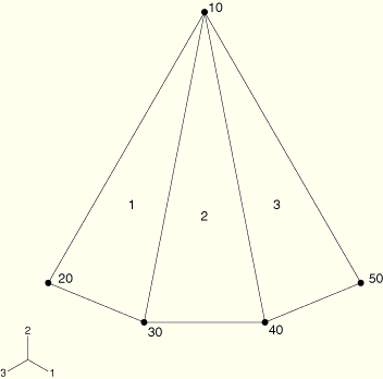
Consider the three element model in Figure 23.6.3–1. Elements 1, 2, and 3 share a common node, node 10, with no user-specified normal defined.
In the first scenario, suppose that at node 10 the normal for element 2 is within 20° of both elements 1 and 3, but the normals for elements 1 and 3 are not within 20° of each other. In this case, each element is assigned its own normal: one is stored as part of the node definition and two are stored as user-specified normals.
In the second scenario, suppose that at node 10 the normal for element 2 is within 20° of both elements 1 and 3 and the normals for elements 1 and 3 are within 20° of each other. In this case, a single average normal for elements 1, 2, and 3 would be computed and stored as part of the node definition.
In the last scenario, suppose that at node 10 the normal for element 2 is within 20° of element 1 but the normal of element 3 is not within 20° of either element 1 or 2. In this case, an average normal is computed and stored for elements 1, and 2 and the normal for element 3 is stored by itself: one is stored as part of the node definition and the other is stored as a user-specified normal.
In a coarse mesh this algorithm may introduce fold lines where the shell is smooth, or it may create a smooth shell where there should be a fold if the angle of the fold line is less than 20°. Difficulties in large-displacement shell analysis are sometimes caused by false fold lines introduced by coarse meshing. To model a smooth shell, the mesh should be refined enough to create unique nodal normals or the normals must be defined as part of the node definition or by a user-specified normal. To model plates or shells with fold lines, you should define user-specified normals.
Normal definitions can be checked by examining the analysis input file processor output. The direction cosines of the reference normal associated with a node are listed under the NODE DEFINITIONS output in the data (.dat) file. User-specified normals are listed under the NORMAL DEFINITIONS output in the data file.
This discussion applies to conventional shell elements only. Continuum shell elements define a top and bottom surface around the structural body being modeled. The notion of a shell reference surface is not applicable for these types of elements.
The reference surface for conventional shell elements is defined by the shell's nodes and normal definitions. When modeling with shell elements, the reference surface is typically coincident with the shell's midsurface. However, many situations arise in which it is more convenient to define the reference surface as offset from the shell's midsurface. For example, CAD surfaces usually represent either the top or bottom surface of the shell. In this case it may be easier to define the reference surface to be coincident with the CAD surface and, therefore, offset from the shell's midsurface.
Shell offsets can also be used to define a more precise surface geometry for contact problems where shell thickness is important. Another situation where the offset from the midsurface may be important is when a shell with continuously varying thickness is modeled. In this case if one surface of the shell is smooth while the other surface is rough, as in some aircraft structures, using the smooth surface as the reference surface, with an offset of half the shell's thickness from the midsurface, will represent the physical geometry more accurately. The use of the midsurface as the reference surface for this case is much more complicated and may result in an inaccurate model.
You can introduce offsets in the section definitions for both shell sections integrated during the analysis and general shell sections. The offset value is defined as a fraction of the shell thickness measured from the shell's midsurface to the shell's reference surface. See “Using a shell section integrated during the analysis to define the section behavior,” Section 23.6.5, and “Using a general shell section to define the section behavior,” Section 23.6.6, for details.
Offsets can also be defined on an element-by-element basis with an element property assignment. See “Assigning element properties on an element-by-element basis,” Section 21.1.5, for details.
The degrees of freedom for the shell are associated with the reference surface. All kinematic quantities, including the element's area, are calculated there. Any loading in the plane of the reference surface will, therefore, cause both membrane forces and bending moments when a nonzero offset value is used. Large offset values for curved shells may also lead to a surface integration error, affecting the stiffness, mass, and rotary inertia for the shell section. For stability purposes ABAQUS/Explicit also automatically scales the rotary inertia used for shell elements by a factor proportional to the offset squared, which may result in errors for large offsets. When a large offset from the shell's midsurface is necessary, use multi-point constraints instead (see “General multi-point constraints,” Section 28.2.2).