Products: ABAQUS/Standard ABAQUS/Explicit ABAQUS/CAE

A linear elastic material model:
is valid for small elastic strains (normally less than 5%);
can be isotropic, orthotropic, or fully anisotropic; and
can have properties that depend on temperature and/or other field variables.

The total stress is defined from the total elastic strain as
![]()
The elastic response of a viscoelastic material (“Time domain viscoelasticity,” Section 17.7.1) can be specified by defining either the instantaneous response or the long-term response of the material. To define the instantaneous response, experiments to determine the elastic constants have to be performed within time spans much shorter than the characteristic relaxation time of the material.
| Input File Usage: | *ELASTIC, MODULI=INSTANTANEOUS |
| ABAQUS/CAE Usage: | Property module: material editor: Mechanical |
If, on the other hand, the long-term elastic response is used, data from experiments have to be collected after time spans much longer than the characteristic relaxation time of the viscoelastic material. Long-term elastic response is the default elastic material behavior.
| Input File Usage: | *ELASTIC, MODULI=LONG TERM |
| ABAQUS/CAE Usage: | Property module: material editor: Mechanical |

Depending on the number of symmetry planes for the elastic properties, a material can be classified as either isotropic (an infinite number of symmetry planes passing through every point) or anisotropic (no symmetry planes). Some materials have a restricted number of symmetry planes passing through every point; for example, orthotropic materials have two orthogonal symmetry planes for the elastic properties. The number of independent components of the elasticity tensor ![]() depends on such symmetry properties. You define the level of anisotropy and method of defining the elastic properties, as described below. If the material is anisotropic, a local orientation (“Orientations,” Section 2.2.5) must be used to define the direction of anisotropy.
depends on such symmetry properties. You define the level of anisotropy and method of defining the elastic properties, as described below. If the material is anisotropic, a local orientation (“Orientations,” Section 2.2.5) must be used to define the direction of anisotropy.

Linear elastic materials must satisfy the conditions of material or Drucker stability (see the discussion on material stability in “Hyperelastic behavior of rubberlike materials,” Section 17.5.1). Stability requires that the tensor ![]() be positive definite, which leads to certain restrictions on the values of the elastic constants. The stress-strain relations for several different classes of material symmetries are given below. The appropriate restrictions on the elastic constants stemming from the stability criterion are also given.
be positive definite, which leads to certain restrictions on the values of the elastic constants. The stress-strain relations for several different classes of material symmetries are given below. The appropriate restrictions on the elastic constants stemming from the stability criterion are also given.

The simplest form of linear elasticity is the isotropic case, and the stress-strain relationship is given by

The elastic properties are completely defined by giving the Young's modulus, E, and the Poisson's ratio, ![]() . The shear modulus, G, can be expressed in terms of E and
. The shear modulus, G, can be expressed in terms of E and ![]() as
as ![]() . These parameters can be given as functions of temperature and of other predefined fields, if necessary.
. These parameters can be given as functions of temperature and of other predefined fields, if necessary.
| Input File Usage: | *ELASTIC, TYPE=ISOTROPIC |
| ABAQUS/CAE Usage: | Property module: material editor: Mechanical |
The stability criterion requires that ![]() ,
, ![]() , and
, and ![]() . Values of Poisson's ratio approaching 0.5 result in nearly incompressible behavior. With the exception of plane stress cases (including membranes and shells) or beams and trusses, such values generally require the use of “hybrid” elements in ABAQUS/Standard and generate high frequency noise and result in excessively small stable time increments in ABAQUS/Explicit.
. Values of Poisson's ratio approaching 0.5 result in nearly incompressible behavior. With the exception of plane stress cases (including membranes and shells) or beams and trusses, such values generally require the use of “hybrid” elements in ABAQUS/Standard and generate high frequency noise and result in excessively small stable time increments in ABAQUS/Explicit.

Linear elasticity in an orthotropic material is most easily defined by giving the “engineering constants”: the three moduli ![]() ,
, ![]() ,
, ![]() ; Poisson's ratios
; Poisson's ratios ![]() ,
, ![]() ,
, ![]() ; and the shear moduli
; and the shear moduli ![]() ,
, ![]() , and
, and ![]() associated with the material's principal directions. These moduli define the elastic compliance according to
associated with the material's principal directions. These moduli define the elastic compliance according to

| Input File Usage: | *ELASTIC, TYPE=ENGINEERING CONSTANTS |
| ABAQUS/CAE Usage: | Property module: material editor: Mechanical |

A special subclass of orthotropy is transverse isotropy, which is characterized by a plane of isotropy at every point in the material. Assuming the 1–2 plane to be the plane of isotropy at every point, transverse isotropy requires that ![]() =
=![]() =
=![]() ,
, ![]() =
=![]() =
=![]() ,
, ![]() =
=![]() =
=![]() , and
, and ![]() =
=![]() =
=![]() , where p and t stand for “in-plane” and “transverse,” respectively. Thus, while
, where p and t stand for “in-plane” and “transverse,” respectively. Thus, while ![]() has the physical interpretation of the Poisson's ratio that characterizes the strain in the plane of isotropy resulting from stress normal to it,
has the physical interpretation of the Poisson's ratio that characterizes the strain in the plane of isotropy resulting from stress normal to it, ![]() characterizes the transverse strain in the direction normal to the plane of isotropy resulting from stress in the plane of isotropy. In general, the quantities
characterizes the transverse strain in the direction normal to the plane of isotropy resulting from stress in the plane of isotropy. In general, the quantities ![]() and
and ![]() are not equal and are related by
are not equal and are related by ![]() =
=![]() . The stress-strain laws reduce to
. The stress-strain laws reduce to

| Input File Usage: | *ELASTIC, TYPE=ENGINEERING CONSTANTS |
| ABAQUS/CAE Usage: | Property module: material editor: Mechanical |

Under plane stress conditions, such as in a shell element, only the values of ![]() ,
, ![]() ,
, ![]() ,
, ![]() ,
, ![]() , and
, and ![]() are required to define an orthotropic material. (In all of the plane stress elements in ABAQUS the
are required to define an orthotropic material. (In all of the plane stress elements in ABAQUS the ![]() surface is the surface of plane stress, so that the plane stress condition is
surface is the surface of plane stress, so that the plane stress condition is ![]() .) The shear moduli
.) The shear moduli ![]() and
and ![]() are included because they may be required for modeling transverse shear deformation in a shell. The Poisson's ratio
are included because they may be required for modeling transverse shear deformation in a shell. The Poisson's ratio ![]() is implicitly given as
is implicitly given as ![]() . In this case the stress-strain relations for the in-plane components of the stress and strain are of the form
. In this case the stress-strain relations for the in-plane components of the stress and strain are of the form

| Input File Usage: | *ELASTIC, TYPE=LAMINA |
| ABAQUS/CAE Usage: | Property module: material editor: Mechanical |

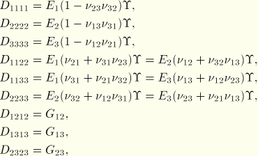
Linear elasticity in an orthotropic material can also be defined by giving the nine independent elastic stiffness parameters, as functions of temperature and other predefined fields, if necessary. In this case the stress-strain relations are of the form


![]()
When the material stiffness parameters (the ![]() ) are given directly, ABAQUS imposes the constraint
) are given directly, ABAQUS imposes the constraint ![]() for the plane stress case to reduce the material's stiffness matrix as required.
for the plane stress case to reduce the material's stiffness matrix as required.
| Input File Usage: | *ELASTIC, TYPE=ORTHOTROPIC |
| ABAQUS/CAE Usage: | Property module: material editor: Mechanical |
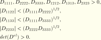
The restrictions on the elastic constants due to material stability are

![]()
These restrictions in terms of the elastic stiffness parameters are equivalent to the restrictions in terms of the “engineering constants.” Incompressible behavior results when the left-hand side of the inequality approaches zero.

For fully anisotropic elasticity 21 independent elastic stiffness parameters are needed. The stress-strain relations are as follows:

When the material stiffness parameters (the ![]() ) are given directly, ABAQUS imposes the constraint
) are given directly, ABAQUS imposes the constraint ![]() for the plane stress case to reduce the material's stiffness matrix as required.
for the plane stress case to reduce the material's stiffness matrix as required.
| Input File Usage: | *ELASTIC, TYPE=ANISOTROPIC |
| ABAQUS/CAE Usage: | Property module: material editor: Mechanical |

For two-dimensional meshed models of solid cross-section Timoshenko beam elements modeled with warping elements (see “Meshed beam cross-sections,” Section 10.4.1), ABAQUS offers a linear elastic material definition that can have two different shear moduli in the user-specified material directions. In the user-specified directions the stress-strain relations are as follows:


| Input File Usage: | *ELASTIC, TYPE=TRACTION |
| ABAQUS/CAE Usage: | Property module: material editor: Mechanical |

For cohesive elements used to model bonded interfaces (see “Defining the constitutive response of cohesive elements using a traction-separation description,” Section 26.5.6) ABAQUS offers an elasticity definition that can be written directly in terms of the nominal tractions and the nominal strains. Both uncoupled and coupled behaviors are supported. For uncoupled behavior each traction component depends only on its conjugate nominal strain, while for coupled behavior the response is more general (as shown below). In the local element directions the stress-strain relations for uncoupled behavior are as follows:


| ABAQUS/CAE Usage: | Use the following option to define uncoupled elastic behavior for cohesive elements: |
Property module: material editor: Mechanical Use the following option to define coupled elastic behavior for cohesive elements: Property module: material editor: Mechanical |

Linear elasticity can be used with any stress/displacement element or coupled temperature-displacement element in ABAQUS. The exceptions are traction elasticity, which can be used only with warping elements and cohesive elements; coupled traction elasticity, which can be used only with cohesive elements; and, in ABAQUS/Explicit, anisotropic elasticity, which is not supported for truss, rebar, and beam elements.
If the material is (almost) incompressible (Poisson's ratio ![]() for isotropic elasticity), hybrid elements should be used in ABAQUS/Standard. Compressible anisotropic elasticity should not be used with second-order hybrid continuum elements: inaccurate results and/or convergence problems may occur.
for isotropic elasticity), hybrid elements should be used in ABAQUS/Standard. Compressible anisotropic elasticity should not be used with second-order hybrid continuum elements: inaccurate results and/or convergence problems may occur.