Products: ABAQUS/Standard ABAQUS/Explicit ABAQUS/CAE
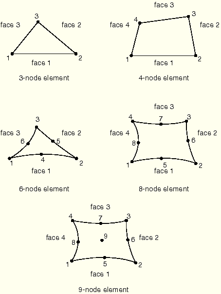
| STRI3(S) | 3-node triangular facet thin shell |
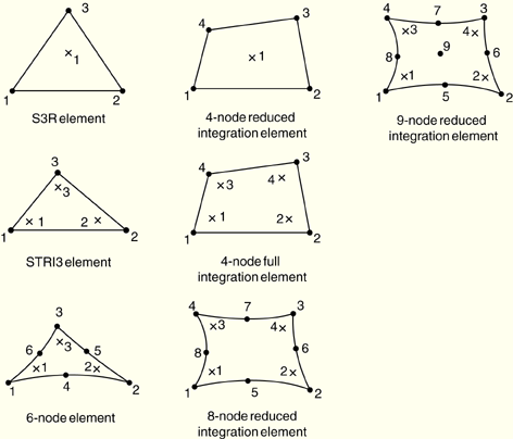
| S3 | 3-node triangular general-purpose shell, finite membrane strains (identical to element S3R) |
| S3R | 3-node triangular general-purpose shell, finite membrane strains (identical to element S3) |
| S3RS(E) | 3-node triangular shell, small membrane strains |
| STRI65(S) | 6-node triangular thin shell, using five degrees of freedom per node |
| S4(S) | 4-node doubly curved general-purpose shell, finite membrane strains |
| S4R | 4-node doubly curved general-purpose shell, reduced integration with hourglass control, finite membrane strains |
| S4RS(E) | 4-node, reduced integration, doubly curved shell with hourglass control, small membrane strains |
| S4RSW(E) | 4-node, reduced integration, doubly curved shell with hourglass control, small membrane strains, warping considered in small-strain formulation |
| S4R5(S) | 4-node doubly curved thin shell, reduced integration with hourglass control, using five degrees of freedom per node |
| S8R(S) | 8-node doubly curved thick shell, reduced integration |
| S8R5(S) | 8-node doubly curved thin shell, reduced integration, using five degrees of freedom per node |
| S9R5(S) | 9-node doubly curved thin shell, reduced integration, using five degrees of freedom per node |
1, 2, 3, 4, 5, 6 for STRI3, S3R, S3RS, S4, S4R, S4RS, S4RSW, S8R
1, 2, 3 and two in-surface rotations for STRI65, S4R5, S8R5, S9R5 at most nodes
1, 2, 3, 4, 5, 6 for STRI65, S4R5, S8R5, S9R5 at any node that
has a boundary condition on a rotational degree of freedom;
is involved in a multi-point constraint that uses rotational degrees of freedom;
is attached to a beam or to a shell element that uses six degrees of freedom at all nodes (such as S4R, S8R, STRI3, etc.);
is a point where different elements have different surface normals (user-specified normal definitions or normal definitions created by ABAQUS because the surface is folded); or
is loaded with moments.
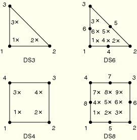
| DS3(S) | 3-node triangular shell |
| DS4(S) | 4-node quadrilateral shell |
| DS6(S) | 6-node triangular shell |
| DS8(S) | 8-node quadrilateral shell |
11, 12, etc. (temperatures through the thickness as described in “Choosing a shell element,” Section 23.6.2)
| S8RT(S) | 8-node thick shell, biquadratic displacement, bilinear temperature in the shell surface |
1, 2, 3, 4, 5, 6 at all eight nodes
11, 12, 13, etc. (temperatures through the thickness as described in “Choosing a shell element,” Section 23.6.2) at the corner nodes only
![]() and, optionally for shells with displacement degrees of freedom in ABAQUS/Standard,
and, optionally for shells with displacement degrees of freedom in ABAQUS/Standard, ![]() , the direction cosines of the shell normal at the node.
, the direction cosines of the shell normal at the node.
Shell thicknesses, offsets, material orientations, and section stiffnesses can be defined on an element-by-element basis. See “Assigning element properties on an element-by-element basis,” Section 21.1.5.
| Input File Usage: | Use either of the following options for stress/displacement elements: |
*SHELL SECTION
*SHELL GENERAL SECTION
Use the following option for heat transfer or coupled temperature-displacement elements: *SHELL SECTION In addition, use the following option for variable thickness shells: *NODAL THICKNESS |
| ABAQUS/CAE Usage: | Property module: Create Section: select Shell as the section Category and Homogeneous or Composite as the section Type |
You cannot define variable thickness shells in ABAQUS/CAE. |
Distributed loads are available for all elements with displacement degrees of freedom. They are specified as described in “Distributed loads,” Section 27.4.3.
Body forces, centrifugal loads, and Coriolis forces must be given as force per unit area if the equivalent section properties are specified directly as part of the general shell section definition.
Load ID (*DLOAD): BX
ABAQUS/CAE Load/Interaction: Body force
Units: FL–3
Description: Body force (give magnitude as force per unit volume) in the global X-direction.
Load ID (*DLOAD): BY
ABAQUS/CAE Load/Interaction: Body force
Units: FL–3
Description: Body force (give magnitude as force per unit volume) in the global Y-direction.
Load ID (*DLOAD): BZ
ABAQUS/CAE Load/Interaction: Body force
Units: FL–3
Description: Body force (give magnitude as force per unit volume) in the global Z-direction.
Load ID (*DLOAD): BXNU
ABAQUS/CAE Load/Interaction: Body force
Units: FL–3
Description: Nonuniform body force (give magnitude as force per unit volume) in the global X-direction, with magnitude supplied via user subroutine DLOAD in ABAQUS/Standard and VDLOAD in ABAQUS/Explicit.
Load ID (*DLOAD): BYNU
ABAQUS/CAE Load/Interaction: Body force
Units: FL–3
Description: Nonuniform body force (give magnitude as force per unit volume) in the global Y-direction, with magnitude supplied via user subroutine DLOAD in ABAQUS/Standard and VDLOAD in ABAQUS/Explicit.
Load ID (*DLOAD): BZNU
ABAQUS/CAE Load/Interaction: Body force
Units: FL–3
Description: Nonuniform body force (give magnitude as force per unit volume) in the global Z-direction, with magnitude supplied via user subroutine DLOAD in ABAQUS/Standard and VDLOAD in ABAQUS/Explicit.
Load ID (*DLOAD): CENT(S)
ABAQUS/CAE Load/Interaction: Not supported
Units: FL–4 (ML–3T–2)
Description: Centrifugal load (magnitude defined as ![]() , where
, where ![]() is the mass density and
is the mass density and ![]() is the angular speed).
is the angular speed).
Load ID (*DLOAD): CENTRIF(S)
ABAQUS/CAE Load/Interaction: Rotational body force
Units: T–2
Description: Centrifugal load (magnitude is input as ![]() , where
, where ![]() is the angular speed).
is the angular speed).
Load ID (*DLOAD): CORIO(S)
ABAQUS/CAE Load/Interaction: Not supported
Units: FL–4T (ML–3T–1)
Description: Coriolis force (magnitude input ![]() , where
, where ![]() is the mass density and
is the mass density and ![]() is the angular speed). The load stiffness due to Coriolis loading is not accounted for in direct steady-state dynamics analysis.
is the angular speed). The load stiffness due to Coriolis loading is not accounted for in direct steady-state dynamics analysis.
Load ID (*DLOAD): EDLDn
ABAQUS/CAE Load/Interaction: Not supported
Units: FL–1
Description: General traction on edge n.
Load ID (*DLOAD): EDLDnNU(S)
ABAQUS/CAE Load/Interaction: Not supported
Units: FL–1
Description: Nonuniform general traction on edge n with magnitude and direction supplied via user subroutine UTRACLOAD.
Load ID (*DLOAD): EDMOMn
ABAQUS/CAE Load/Interaction: Not supported
Units: F
Description: Moment on edge n.
Load ID (*DLOAD): EDMOMnNU(S)
ABAQUS/CAE Load/Interaction: Not supported
Units: F
Description: Nonuniform moment on edge n with magnitude supplied via user subroutine UTRACLOAD.
Load ID (*DLOAD): EDNORn
ABAQUS/CAE Load/Interaction: Not supported
Units: FL–1
Description: Normal traction on edge n.
Load ID (*DLOAD): EDNORnNU(S)
ABAQUS/CAE Load/Interaction: Not supported
Units: FL–1
Description: Nonuniform normal traction on edge n with magnitude supplied via user subroutine UTRACLOAD.
Load ID (*DLOAD): EDSHRn
ABAQUS/CAE Load/Interaction: Not supported
Units: FL–1
Description: Shear traction on edge n.
Load ID (*DLOAD): EDSHRnNU(S)
ABAQUS/CAE Load/Interaction: Not supported
Units: FL–1
Description: Nonuniform shear traction on edge n with magnitude supplied via user subroutine UTRACLOAD.
Load ID (*DLOAD): EDTRAn
ABAQUS/CAE Load/Interaction: Not supported
Units: FL–1
Description: Transverse traction on edge n.
Load ID (*DLOAD): EDTRAnNU(S)
ABAQUS/CAE Load/Interaction: Not supported
Units: FL–1
Description: Nonuniform transverse traction on edge n with magnitude supplied via user subroutine UTRACLOAD.
Load ID (*DLOAD): GRAV
ABAQUS/CAE Load/Interaction: Gravity
Units: LT–2
Description: Gravity loading in a specified direction (magnitude is input as acceleration).
Load ID (*DLOAD): HP(S)
ABAQUS/CAE Load/Interaction: Not supported
Units: FL–2
Description: Hydrostatic pressure applied to the element reference surface and linear in global Z. The pressure is positive in the direction of the positive element normal.
Load ID (*DLOAD): P
ABAQUS/CAE Load/Interaction: Not supported
Units: FL–2
Description: Pressure applied to the element reference surface. The pressure is positive in the direction of the positive element normal.
Load ID (*DLOAD): PNU
ABAQUS/CAE Load/Interaction: Not supported
Units: FL–2
Description: Nonuniform pressure applied to the element reference surface with magnitude supplied via user subroutine DLOAD in ABAQUS/Standard and VDLOAD in ABAQUS/Explicit. The pressure is positive in the direction of the positive element normal.
Load ID (*DLOAD): ROTA(S)
ABAQUS/CAE Load/Interaction: Rotational body force
Units: T–2
Description: Rotary acceleration load (magnitude is input as ![]() , where
, where ![]() is the rotary acceleration).
is the rotary acceleration).
Load ID (*DLOAD): SBF(E)
ABAQUS/CAE Load/Interaction: Not supported
Units: FL–5T
Description: Stagnation body force in global X-, Y-, and Z-directions.
Load ID (*DLOAD): SP(E)
ABAQUS/CAE Load/Interaction: Pressure
Units: FL–4T2
Description: Stagnation pressure applied to the element reference surface.
Load ID (*DLOAD): TRSHR
ABAQUS/CAE Load/Interaction: Not supported
Units: FL–2
Description: Shear traction on the element reference surface.
Load ID (*DLOAD): TRSHRNU(S)
ABAQUS/CAE Load/Interaction: Not supported
Units: FL–2
Description: Nonuniform shear traction on the element reference surface with magnitude and direction supplied via user subroutine UTRACLOAD.
Load ID (*DLOAD): TRVEC
ABAQUS/CAE Load/Interaction: Not supported
Units: FL–2
Description: General traction on the element reference surface.
Load ID (*DLOAD): TRVECNU(S)
ABAQUS/CAE Load/Interaction: Not supported
Units: FL–2
Description: Nonuniform general traction on the element reference surface with magnitude and direction supplied via user subroutine UTRACLOAD.
Load ID (*DLOAD): VBF(E)
ABAQUS/CAE Load/Interaction: Not supported
Units: FL–4T
Description: Viscous body force in global X-, Y-, and Z-directions.
Load ID (*DLOAD): VP(E)
ABAQUS/CAE Load/Interaction: Pressure
Units: FL–3T
Description: Viscous surface pressure. The viscous pressure is proportional to the velocity normal to the element face and opposing the motion.
Foundations are available for ABAQUS/Standard elements with displacement degrees of freedom. They are specified as described in “Element foundations,” Section 2.2.2.
Load ID (*FOUNDATION): F(S)
ABAQUS/CAE Load/Interaction: Elastic foundation
Units: FL–3
Description: Elastic foundation in the direction of the shell normal.
Distributed heat fluxes are available for elements with temperature degrees of freedom. They are specified as described in “Thermal loads,” Section 27.4.4.
Load ID (*DFLUX): BF(S)
ABAQUS/CAE Load/Interaction: Body heat flux
Units: JL–3 T–1
Description: Body heat flux per unit volume.
Load ID (*DFLUX): BFNU(S)
ABAQUS/CAE Load/Interaction: Body heat flux
Units: JL–3 T–1
Description: Nonuniform body heat flux per unit volume with magnitude supplied via user subroutine DFLUX.
Load ID (*DFLUX): SNEG(S)
ABAQUS/CAE Load/Interaction: Not supported
Units: JL–2 T–1
Description: Surface heat flux per unit area into the bottom face of the element.
Load ID (*DFLUX): SPOS(S)
ABAQUS/CAE Load/Interaction: Not supported
Units: JL–2 T–1
Description: Surface heat flux per unit area into the top face of the element.
Load ID (*DFLUX): SNEGNU(S)
ABAQUS/CAE Load/Interaction: Not supported
Units: JL–2 T–1
Description: Nonuniform surface heat flux per unit area into the bottom face of the element with magnitude supplied via user subroutine DFLUX.
Load ID (*DFLUX): SPOSNU(S)
ABAQUS/CAE Load/Interaction: Not supported
Units: JL–2 T–1
Description: Nonuniform surface heat flux per unit area into the top face of the element with magnitude supplied via user subroutine DFLUX.
Film conditions are available for elements with temperature degrees of freedom. They are specified as described in “Thermal loads,” Section 27.4.4.
Load ID (*FILM): FNEG(S)
ABAQUS/CAE Load/Interaction: Surface film condition
Units: JL–2 T–1![]() –1
–1
Description: Film coefficient and sink temperature (units of ![]() ) provided on the bottom face of the element.
) provided on the bottom face of the element.
Load ID (*FILM): FPOS(S)
ABAQUS/CAE Load/Interaction: Surface film condition
Units: JL–2 T–1![]() –1
–1
Description: Film coefficient and sink temperature (units of ![]() ) provided on the top face of the element.
) provided on the top face of the element.
Load ID (*FILM): FNEGNU(S)
ABAQUS/CAE Load/Interaction: Not supported
Units: JL–2 T–1![]() –1
–1
Description: Nonuniform film coefficient and sink temperature (units of ![]() ) provided on the bottom face of the element with magnitude supplied via user subroutine FILM.
) provided on the bottom face of the element with magnitude supplied via user subroutine FILM.
Load ID (*FILM): FPOSNU(S)
ABAQUS/CAE Load/Interaction: Not supported
Units: JL–2 T–1![]() –1
–1
Description: Nonuniform film coefficient and sink temperature (units of ![]() ) provided on the top face of the element with magnitude supplied via user subroutine FILM.
) provided on the top face of the element with magnitude supplied via user subroutine FILM.
Radiation conditions are available for elements with temperature degrees of freedom. They are specified as described in “Thermal loads,” Section 27.4.4.
Load ID (*RADIATE): RNEG(S)
ABAQUS/CAE Load/Interaction: Not supported
Units: Dimensionless
Description: Emissivity and sink temperature (units of ![]() ) provided for the bottom face of the shell.
) provided for the bottom face of the shell.
Load ID (*RADIATE): RPOS(S)
ABAQUS/CAE Load/Interaction: Not supported
Units: Dimensionless
Description: Emissivity and sink temperature (units of ![]() ) provided for the top face of the shell.
) provided for the top face of the shell.
Surface-based distributed loads are available for all elements with displacement degrees of freedom. They are specified as described in “Distributed loads,” Section 27.4.3.
Load ID (*DSLOAD): EDLD
ABAQUS/CAE Load/Interaction: Shell edge load
Units: FL–1
Description: General traction on edge-based surface.
Load ID (*DSLOAD): EDLDNU(S)
ABAQUS/CAE Load/Interaction: Not supported
Units: FL–1
Description: Nonuniform general traction on edge-based surface with magnitude and direction supplied via user subroutine UTRACLOAD.
Load ID (*DSLOAD): EDMOM
ABAQUS/CAE Load/Interaction: Shell edge load
Units: F
Description: Moment on edge-based surface.
Load ID (*DSLOAD): EDMOMNU(S)
ABAQUS/CAE Load/Interaction: Not supported
Units: F
Description: Nonuniform moment on edge-based surface with magnitude supplied via user subroutine UTRACLOAD.
Load ID (*DSLOAD): EDNOR
ABAQUS/CAE Load/Interaction: Shell edge load
Units: FL–1
Description: Normal traction on edge-based surface.
Load ID (*DSLOAD): EDNORNU(S)
ABAQUS/CAE Load/Interaction: Not supported
Units: FL–1
Description: Nonuniform normal traction on edge-based surface with magnitude supplied via user subroutine UTRACLOAD.
Load ID (*DSLOAD): EDSHR
ABAQUS/CAE Load/Interaction: Shell edge load
Units: FL–1
Description: Shear traction on edge-based surface.
Load ID (*DSLOAD): EDSHRNU(S)
ABAQUS/CAE Load/Interaction: Not supported
Units: FL–1
Description: Nonuniform shear traction on edge-based surface with magnitude supplied via user subroutine UTRACLOAD.
Load ID (*DSLOAD): EDTRA
ABAQUS/CAE Load/Interaction: Shell edge load
Units: FL–1
Description: Transverse traction on edge-based surface.
Load ID (*DSLOAD): EDTRANU(S)
ABAQUS/CAE Load/Interaction: Not supported
Units: FL–1
Description: Nonuniform transverse traction on edge-based surface with magnitude supplied via user subroutine UTRACLOAD.
Load ID (*DSLOAD): HP(S)
ABAQUS/CAE Load/Interaction: Pressure
Units: FL–2
Description: Hydrostatic pressure on the element reference surface and linear in global Z. The pressure is positive in the direction opposite to the surface normal.
Load ID (*DSLOAD): P
ABAQUS/CAE Load/Interaction: Pressure
Units: FL–2
Description: Pressure on the element reference surface. The pressure is positive in the direction opposite to the surface normal.
Load ID (*DSLOAD): PNU
ABAQUS/CAE Load/Interaction: Pressure
Units: FL–2
Description: Nonuniform pressure on the element reference surface with magnitude supplied via user subroutine DLOAD in ABAQUS/Standard and VDLOAD in ABAQUS/Explicit. The pressure is positive in the direction opposite to the surface normal.
Load ID (*DSLOAD): SP(E)
ABAQUS/CAE Load/Interaction: Pressure
Units: FL–4T2
Description: Stagnation pressure applied to the element reference surface.
Load ID (*DSLOAD): TRSHR
ABAQUS/CAE Load/Interaction: Surface traction
Units: FL–2
Description: Shear traction on the element reference surface.
Load ID (*DSLOAD): TRSHRNU(S)
ABAQUS/CAE Load/Interaction: Not supported
Units: FL–2
Description: Nonuniform shear traction on the element reference surface with magnitude and direction supplied via user subroutine UTRACLOAD.
Load ID (*DSLOAD): TRVEC
ABAQUS/CAE Load/Interaction: Surface traction
Units: FL–2
Description: General traction on the element reference surface.
Load ID (*DSLOAD): TRVECNU(S)
ABAQUS/CAE Load/Interaction: Not supported
Units: FL–2
Description: Nonuniform general traction on the element reference surface with magnitude and direction supplied via user subroutine UTRACLOAD.
Load ID (*DSLOAD): VP(E)
ABAQUS/CAE Load/Interaction: Pressure
Units: FL–3T
Description: Viscous surface pressure. The viscous pressure is proportional to the velocity normal to the element face and opposing the motion.
Surface-based distributed heat fluxes are available for elements with temperature degrees of freedom. They are specified as described in “Thermal loads,” Section 27.4.4.
Load ID (*DSFLUX): S(S)
ABAQUS/CAE Load/Interaction: Surface heat flux
Units: JL–2 T–1
Description: Surface heat flux per unit area into the element surface.
Load ID (*DSFLUX): SNU(S)
ABAQUS/CAE Load/Interaction: Surface heat flux
Units: JL–2 T–1
Description: Nonuniform surface heat flux per unit area into the element surface with magnitude supplied via user subroutine DFLUX.
Surface-based film conditions are available for elements with temperature degrees of freedom. They are specified as described in “Thermal loads,” Section 27.4.4.
Load ID (*SFILM): F(S)
ABAQUS/CAE Load/Interaction: Surface film condition
Units: JL–2 T–1![]() –1
–1
Description: Film coefficient and sink temperature (units of ![]() ) provided on the element surface.
) provided on the element surface.
Load ID (*SFILM): FNU(S)
ABAQUS/CAE Load/Interaction: Surface film condition
Units: JL–2 T–1![]() –1
–1
Description: Nonuniform film coefficient and sink temperature (units of ![]() ) provided on the element surface with magnitude supplied via user subroutine FILM.
) provided on the element surface with magnitude supplied via user subroutine FILM.
Surface-based radiation conditions are available for elements with temperature degrees of freedom. They are specified as described in “Thermal loads,” Section 27.4.4.
Load ID (*SRADIATE): R(S)
ABAQUS/CAE Load/Interaction: Surface radiation to ambient
Units: Dimensionless
Description: Emissivity and sink temperature (units of ![]() ) provided for the element surface.
) provided for the element surface.
Surface-based incident wave loads are available. They are specified as described in “Acoustic, shock, and coupled acoustic-structural analysis,” Section 6.9.1. If the incident wave field includes a reflection off a plane outside the boundaries of the mesh, this effect can be included.
If a local coordinate system is not assigned to the element, the stress/strain components, as well as the section forces/strains, are in the default directions on the surface defined by the convention given in “Conventions,” Section 1.2.2. If a local coordinate system is assigned to the element through either the section definition (“Orientations,” Section 2.2.5) or an element property assignment (“Assigning element properties on an element-by-element basis,” Section 21.1.5), the stress/strain components and the section forces/strains are in the surface directions defined by the local coordinate system.
In large-displacement problems with elements that allow finite membrane strains in ABAQUS/Standard and in all problems in ABAQUS/Explicit, the local directions defined in the reference configuration are rotated into the current configuration by the average material rotation.
Stress and other tensors (including strain tensors) are available for elements with displacement degrees of freedom. All tensors have the same components. For example, the stress components are as follows:
S11 | Local |
S22 | Local |
S12 | Local |
Available for elements with displacement degrees of freedom.
SF1 | Direct membrane force per unit width in local 1-direction. |
SF2 | Direct membrane force per unit width in local 2-direction. |
SF3 | Shear membrane force per unit width in local 1–2 plane. |
SF4 | Transverse shear force per unit width in local 1-direction (available only for S3/S3R, S3RS, S4, S4R, S4RS, S4RSW, S8R, and S8RT). |
SF5 | Transverse shear force per unit width in local 2-direction (available only for S3/S3R, S3RS, S4, S4R, S4RS, S4RSW, S8R, and S8RT). |
SM1 | Bending moment force per unit width about local 2-axis. |
SM2 | Bending moment force per unit width about local 1-axis. |
SM3 | Twisting moment force per unit width in local 1–2 plane. |
The section force and moment resultants per unit length in the normal basis directions in a given shell section of thickness h can be defined on this basis as
The section force SF6, which is the integral of ![]() through the shell thickness, is reported only for finite-strain shell elements and is zero because of the plane stress constitutive assumption. The total number of attributes written to the results file for finite-strain shell elements is 9; SF6 is the sixth attribute.
through the shell thickness, is reported only for finite-strain shell elements and is zero because of the plane stress constitutive assumption. The total number of attributes written to the results file for finite-strain shell elements is 9; SF6 is the sixth attribute.
Available for elements with displacement degrees of freedom.
SSAVG1 | Average membrane stress in local 1-direction. |
SSAVG2 | Average membrane stress in local 2-direction. |
SSAVG3 | Average membrane stress in local 1–2 plane. |
SSAVG4 | Average transverse shear stress in local 1-direction. |
SSAVG5 | Average transverse shear stress in local 2-direction. |
The average section stresses are defined as
![]()
Available for elements with displacement degrees of freedom.
SE1 | Direct membrane strain in local 1-direction. |
SE2 | Direct membrane strain in local 2-direction. |
SE3 | Shear membrane strain in local 1–2 plane. |
SE4 | Transverse shear strain in the local 1-direction (available only for S3/S3R, S3RS, S4, S4R, S4RS, S4RSW, S8R, and S8RT). |
SE5 | Transverse shear strain in the local 2-direction (available only for S3/S3R, S3RS, S4, S4R, S4RS, S4RSW, S8R, and S8RT). |
SE6 | Strain in the thickness direction (available only for S3/S3R, S3RS, S4, S4R, S4RS, and S4RSW). |
SK1 | Curvature change about local 1-axis. |
SK2 | Curvature change about local 2-axis. |
SK3 | Surface twist in local 1–2 plane. |
The local directions are defined in “Shell elements: overview,” Section 23.6.1.
STH | Shell thickness, which is the current section thickness for S3/S3R, S3RS, S4, S4R, S4RS, and S4RSW elements. |
Available for S3/S3R, S3RS, S4, S4R, S4RS, S4RSW, S8R, and S8RT elements.
TSHR13 | 13-component of transverse shear stress. |
TSHR23 | 23-component of transverse shear stress. |
Estimates of the transverse shear stresses are available at section integration points as output variables TSHR13 or TSHR23 for both Simpson's rule and Gauss quadrature. For Simpson's rule output of variables TSHR13 or TSHR23 should be requested at nondefault section points, since the default output is at section point 1 of the shell section where the transverse shear stresses vanish. For the small-strain elements in ABAQUS/Explicit, transverse shear stress distributions are assumed constant for non-composite sections and piecewise constant for composite sections; therefore, transverse shear stresses at integration points should be interpreted accordingly.
For element type S4 the transverse shear calculation is performed at the center of the element and assumed constant over the element. Hence, transverse shear strain, force, and stress will not vary over the area of the element.
For numerically integrated shell sections (with the exception of small-strain shells in ABAQUS/Explicit), estimates of the interlaminar shear stresses in composite sections—i.e., the transverse shear stresses at the interface between two composite layers—can be obtained only by using Simpson's rule. With Gauss quadrature no section integration point exists at the interface between composite layers.
Unlike the S11, S22, and S12 in-plane stress components, transverse shear stress components TSHR13 and TSHR23 are not calculated from the constitutive behavior at points through the shell section. They are estimated by matching the elastic strain energy associated with shear deformation of the shell section with that based on piecewise quadratic variation of the transverse shear stress across the section, under conditions of bending about one axis (see “Transverse shear stiffness in composite shells and offsets from the midsurface,” Section 3.6.8 of the ABAQUS Theory Manual). Therefore, interlaminar shear stress calculation is supported only when the elastic material model is used for each layer of the shell section. If you specify the transverse shear stiffness values, interlaminar shear stress output is not available.