Product: ABAQUS/Standard
For an axisymmetric reference geometry where axisymmetric deformation is expected, use regular axisymmetric elements (see “Axisymmetric shell element library,” Section 23.6.9). For an axisymmetric reference geometry where nonaxisymmetric deformation is expected and the thickness to characteristic radius is high or through the thickness detail is required, use CAXA-type elements (see “Axisymmetric solid elements with nonlinear, asymmetric deformation,” Section 22.1.7).
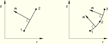
Coordinate 1 is r, coordinate 2 is z. The r-direction corresponds to the global X-direction in the ![]() plane and the global Y-direction in the
plane and the global Y-direction in the ![]() plane, and the z-direction corresponds to the global Z-direction. Coordinate 1 should be greater than or equal to zero.
plane, and the z-direction corresponds to the global Z-direction. Coordinate 1 should be greater than or equal to zero.
Degree of freedom 1 is ![]() , degree of freedom 2 is
, degree of freedom 2 is ![]() , degree of freedom 6 is rotation in the r–z plane.
, degree of freedom 6 is rotation in the r–z plane.
Even though the symmetry in the r–z plane at ![]() allows the modeling of half of the initially axisymmetric structure, the loading must be specified as the total load on the full axisymmetric body. Consider, for example, a cylindrical shell loaded by a unit uniform axial force. To produce a unit load on a SAXA element with four modes, the nodal forces are 1/8, 1/4, 1/4, 1/4, and 1/8 at
allows the modeling of half of the initially axisymmetric structure, the loading must be specified as the total load on the full axisymmetric body. Consider, for example, a cylindrical shell loaded by a unit uniform axial force. To produce a unit load on a SAXA element with four modes, the nodal forces are 1/8, 1/4, 1/4, 1/4, and 1/8 at ![]() ,
, ![]() ,
, ![]() ,
, ![]() , and
, and ![]() , respectively.
, respectively.
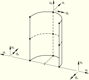
The meridional direction is the direction tangent to the element in the r–z plane; that is, the meridional direction is along the line that is rotated about the axis of symmetry to generate the full three-dimensional body.
The circumferential or hoop direction is the direction normal to the r–z plane.
| SAXA1N | Linear interpolation, Fourier shell element with 2 nodes in the meridional direction and N Fourier modes |
| SAXA2N | Quadratic interpolation, Fourier shell element with 3 nodes in the meridional direction and N Fourier modes |
1, 2, 6
See Figure 23.6.10–1 for the positive nodal displacement and rotation directions. The nodal rotation, ![]() , is consistent with the SAX elements; however, a positive nodal rotation is in the negative
, is consistent with the SAX elements; however, a positive nodal rotation is in the negative ![]() -direction.
-direction.
r, z (given in the r–z plane for ![]() )
)
The two direction cosines, ![]() and
and ![]() , of the nodal normal field can be specified either in the nodal data or by a user-specified normal definition (see “Normal definitions at nodes,” Section 2.1.4).
, of the nodal normal field can be specified either in the nodal data or by a user-specified normal definition (see “Normal definitions at nodes,” Section 2.1.4).
If a general shell section is used and the section stiffness matrix is given directly, a full 6 × 6 section stiffness should be specified (i.e., 21 constants as for a three-dimensional shell).
Shell thicknesses, offsets, and section stiffnesses can be defined on an element-by-element basis. See “Assigning element properties on an element-by-element basis,” Section 21.1.5.
| Input File Usage: | Use either of the following options: |
*SHELL SECTION
*SHELL GENERAL SECTION
In addition, use the following option for variable thickness shells: *NODAL THICKNESS |
Distributed loads are specified as described in “Distributed loads,” Section 27.4.3.
Distributed load magnitudes are per unit area or per unit volume. They do not need to be multiplied by ![]() times the radius.
times the radius.
Load ID (*DLOAD): BX
Units: FL–3
Description: Body force per unit volume in the global X-direction.
Load ID (*DLOAD): BZ
Units: FL–3
Description: Body force per unit volume in the global Z-direction.
Load ID (*DLOAD): BXNU
Units: FL–3
Description: Nonuniform body force in the global X-direction with magnitude supplied via user subroutine DLOAD.
Load ID (*DLOAD): BZNU
Units: FL–3
Description: Nonuniform body force in the global Z-direction with magnitude supplied via user subroutine DLOAD.
Load ID (*DLOAD): P
Units: FL–2
Description: Pressure on the shell surface.
Load ID (*DLOAD): PNU
Units: FL–2
Description: Nonuniform pressure on the shell surface with magnitude supplied via user subroutine DLOAD.
Load ID (*DLOAD): HP
Units: FL–2
Description: Hydrostatic pressure on the shell surface, linear in the global Z-direction.
The numerical integration with respect to ![]() employs the trapezoidal rule. There are
employs the trapezoidal rule. There are ![]() equally spaced integration planes in the element, including the
equally spaced integration planes in the element, including the ![]() and
and ![]() planes, with N being the number of Fourier modes. Consequently, the radial nodal forces corresponding to pressure loads applied in the circumferential direction are distributed in this direction in the ratio of
planes, with N being the number of Fourier modes. Consequently, the radial nodal forces corresponding to pressure loads applied in the circumferential direction are distributed in this direction in the ratio of ![]() in the 1 Fourier mode element,
in the 1 Fourier mode element, ![]() in the 2 Fourier mode element, and
in the 2 Fourier mode element, and ![]() in the 4 Fourier mode element. The sum of these consistent nodal forces is equal to the integral of the applied pressure over the full circumference (
in the 4 Fourier mode element. The sum of these consistent nodal forces is equal to the integral of the applied pressure over the full circumference (![]() ).
).
Stress and other tensors (including strain tensors) are available for elements with displacement degrees of freedom. All tensors have the same components. For example, the stress components are as follows:
S11 | Meridional stress. |
S22 | Hoop (circumferential) stress. |
S12 | Local 12 shear stress (zero at |
SF1 | Direct membrane force per unit width in local 1-direction. |
SF2 | Direct membrane force per unit width in local 2-direction. |
SF3 | Shear membrane force per unit width in local 1–2 plane. |
SF4 | Integrated stress in the thickness direction; always zero. |
SM1 | Bending moment per unit width about local 2-axis. |
SM2 | Bending moment per unit width about local 1-axis. |
SM3 | Twisting moment per unit width in local 1–2 plane. |
SE1 | Direct membrane strain in local 1-direction. |
SE2 | Direct membrane strain in local 2-direction. |
SE3 | Shear membrane strain in local 1–2 plane. |
SE4 | Strain in the thickness direction. |
SK1 | Bending strain in local 1-direction. |
SK2 | Bending strain in local 2-direction. |
SK3 | Twisting strain in local 1–2 plane. |
The section force and moment resultants per unit length in the normal basis directions for a given layer of thickness h can be defined, in components relative to this basis, as:
The local directions are defined in “Defining the initial geometry of conventional shell elements,” Section 23.6.3.
The node ordering in the first generator plane (![]() ) of each element is shown below. You specify the line or curve of nodes in the generator plane just as with the SAX1 and SAX2 elements. Each element must have N more planes of nodes defined, where N is the number of Fourier modes used. ABAQUS/Standard will generate these additional circumferential nodes and number them by adding a constant offset value to the nodes specified in the first plane (see “Element definition,” Section 2.2.1).
) of each element is shown below. You specify the line or curve of nodes in the generator plane just as with the SAX1 and SAX2 elements. Each element must have N more planes of nodes defined, where N is the number of Fourier modes used. ABAQUS/Standard will generate these additional circumferential nodes and number them by adding a constant offset value to the nodes specified in the first plane (see “Element definition,” Section 2.2.1).