Product: ABAQUS/Standard
These elements are intended for analysis of hollow bodies, such as pipes and pressure vessels. They can also be used to model solid bodies, but spurious stresses may occur at zero radius, particularly if transverse shear loads are applied.
Coordinate 1 is r, coordinate 2 is z. Referring to the figures shown in “Choosing the element's dimensionality,” Section 21.1.2, the r-direction corresponds to the global X-direction in the ![]() plane and the negative global Z-direction in the
plane and the negative global Z-direction in the ![]() plane, and the z-direction corresponds to the global Y-direction. Coordinate 1 must be greater than or equal to zero.
plane, and the z-direction corresponds to the global Y-direction. Coordinate 1 must be greater than or equal to zero.
Degree of freedom 1 is ![]() , degree of freedom 2 is
, degree of freedom 2 is ![]() . The
. The ![]() degree of freedom is an internal variable: you cannot control it.
degree of freedom is an internal variable: you cannot control it.
| CAXA4N | Bilinear, Fourier quadrilateral with 4 nodes per r–z plane |
| CAXA4HN | Bilinear, Fourier quadrilateral with 4 nodes per r–z plane, hybrid with constant Fourier pressure |
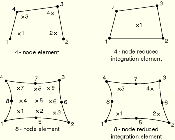
| CAXA4RN | Bilinear, Fourier quadrilateral with 4 nodes per r–z plane, reduced integration in r–z planes with hourglass control |
| CAXA4RHN | Bilinear, Fourier quadrilateral with 4 nodes per r–z plane, reduced integration in r–z planes, hybrid with constant Fourier pressure |
| CAXA8N | Biquadratic, Fourier quadrilateral with 8 nodes per r–z plane |
| CAXA8HN | Biquadratic, Fourier quadrilateral with 8 nodes per |
| CAXA8RN | Biquadratic, Fourier quadrilateral with 8 nodes per r–z plane, reduced integration in r–z planes |
| CAXA8RHN | Biquadratic, Fourier quadrilateral with 8 nodes per r–z plane, reduced integration in r–z planes, hybrid with linear Fourier pressure |
The bilinear elements have 4N and the biquadratic elements 8N additional variables relating to ![]() .
.
Element types CAXA4HN and CAXA4RHN have ![]() additional variables relating to the pressure stress.
additional variables relating to the pressure stress.
Element types CAXA8HN and CAXA8RHN have ![]() additional variables relating to the pressure stress.
additional variables relating to the pressure stress.
Even though the symmetry in the r–z plane at ![]() allows the modeling of half of the initially axisymmetric structure, the loading must be specified as the total load on the full axisymmetric body. Consider, for example, a cylindrical shell loaded by a unit uniform axial force. To produce a unit load on a CAXA element with 4 modes, the nodal forces are 1/8, 1/4, 1/4, 1/4, and 1/8 at
allows the modeling of half of the initially axisymmetric structure, the loading must be specified as the total load on the full axisymmetric body. Consider, for example, a cylindrical shell loaded by a unit uniform axial force. To produce a unit load on a CAXA element with 4 modes, the nodal forces are 1/8, 1/4, 1/4, 1/4, and 1/8 at ![]() ,
, ![]() ,
, ![]() ,
, ![]() , and
, and ![]() , respectively.
, respectively.
Distributed loads are specified as described in “Distributed loads,” Section 27.4.3.
Load ID (*DLOAD): BX
Units: FL–3
Description: Body force per unit volume in the global X-direction.
Load ID (*DLOAD): BZ
Units: FL–3
Description: Body force per unit volume in the z-direction.
Load ID (*DLOAD): BXNU
Units: FL–3
Description: Nonuniform body force in the global X-direction with magnitude supplied via user subroutine DLOAD.
Load ID (*DLOAD): BZNU
Units: FL–3
Description: Nonuniform body force in the z-direction with magnitude supplied via user subroutine DLOAD.
Load ID (*DLOAD): Pn
Units: FL–2
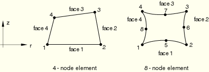
Description: Pressure on face n.
Load ID (*DLOAD): PnNU
Units: FL–2
Description: Nonuniform pressure on face n with magnitude supplied via user subroutine DLOAD.
Load ID (*DLOAD): HPn
Units: FL–2
Description: Hydrostatic pressure on face n, linear in the global z-direction.
Foundations are specified as described in “Element foundations,” Section 2.2.2.
Load ID (*FOUNDATION): Fn
Units: FL–3
Description: Elastic foundation on face n.
Distributed flows are available for elements with pore pressure degrees of freedom. They are specified as described in “Coupled pore fluid diffusion and stress analysis,” Section 6.7.1.
Load ID (*FLOW/ *DFLOW): Qn
Units: F–1L3T–1
Description: Seepage (outward normal flow) proportional to the difference between surface pore pressure and a reference sink pore pressure on face n (units of FL–2).
Load ID (*FLOW/ *DFLOW): QnD
Units: F–1L3T–1
Description: Drainage-only seepage (outward normal flow) proportional to the surface pore pressure on face n only when that pressure is positive.
Load ID (*FLOW/ *DFLOW): QnNU
Units: F–1L3T–1
Description: Nonuniform seepage (outward normal flow) proportional to the difference between surface pore pressure and a reference sink pore pressure on face n (units of FL–2) with magnitude supplied via user subroutine FLOW.
Load ID (*FLOW/ *DFLOW): Sn
Units: LT–1
Description: Prescribed pore fluid velocity (outward from the face) on face n.
Load ID (*FLOW/ *DFLOW): SnNU
Units: LT–1
Description: Nonuniform prescribed pore fluid velocity (outward from the face) on face n with magnitude supplied via user subroutine DFLOW.
The numerical integration with respect to ![]() employs the trapezoidal rule. There are
employs the trapezoidal rule. There are ![]() equally spaced integration planes in the element, including the
equally spaced integration planes in the element, including the ![]() and
and ![]() planes, with N being the number of Fourier modes. Consequently, the radial nodal forces corresponding to pressure loads applied in the circumferential direction are distributed in this direction in the ratio of
planes, with N being the number of Fourier modes. Consequently, the radial nodal forces corresponding to pressure loads applied in the circumferential direction are distributed in this direction in the ratio of ![]() in the 1 Fourier mode element,
in the 1 Fourier mode element, ![]() in the 2 Fourier mode element, and
in the 2 Fourier mode element, and ![]() in the 4 Fourier mode element. The sum of these consistent nodal forces is equal to the integral of the applied pressure over
in the 4 Fourier mode element. The sum of these consistent nodal forces is equal to the integral of the applied pressure over ![]() .
.
Output is as defined below unless a local coordinate system in the r–z plane is assigned to the element through either the section definition (“Orientations,” Section 2.2.5) or an element property assignment (“Assigning element properties on an element-by-element basis,” Section 21.1.5), in which case the components are in the local directions. These local directions rotate with the motion in large-displacement analysis. See “State storage,” Section 1.5.4 of the ABAQUS Theory Manual, for details.
Stress and other tensors (including strain tensors) are available for elements with displacement degrees of freedom. All tensors have the same components. For example, the stress components are as follows:
S11 | Stress in the radial direction or in the local 1-direction. |
S22 | Stress in the axial direction or in the local 2-direction. |
S33 | Hoop direct stress. |
S12 | Shear stress. |
S13 | Shear stress. |
S23 | Shear stress. |
The node ordering in the first r–z plane of each element, at ![]() , is shown below. Each element must have N more planes of nodes defined, where N is the number of Fourier modes. The node ordering is the same in each plane. You can specify the nodes in each plane. Alternatively, you can specify the node ordering in the first r–z plane of an element, and ABAQUS/Standard will generate all other nodes for the element by adding successively a constant offset to each node for each of the N planes of the element (see “Element definition,” Section 2.2.1).
, is shown below. Each element must have N more planes of nodes defined, where N is the number of Fourier modes. The node ordering is the same in each plane. You can specify the nodes in each plane. Alternatively, you can specify the node ordering in the first r–z plane of an element, and ABAQUS/Standard will generate all other nodes for the element by adding successively a constant offset to each node for each of the N planes of the element (see “Element definition,” Section 2.2.1).