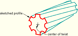
You can choose to include twist during the creation of an extrusion. Twist can be used to create twisted cables, helical gears, and other complex shapes that can be formed by passing a constant cross-section through a sequence of parallel planes. Twist modifies an extrusion by rotating the sketched profile about an axis parallel to the direction of extrusion. The center of twist is an isolated point in the sketched profile; it is the point at which the axis used to twist the extrusion passes through the sketch plane. The pitch defines the extrusion distance in which the profile would be twisted by 360°. You can modify the extrusion profile, extrusion direction, center of twist, and pitch using the Feature Manipulation toolset.
You can add twist during the creation of extruded solid, shell, and cut features. Figure 11–47 illustrates a twisted extrusion.
If you want to create complex shapes in which the sketched profile is revolved rather than extruded, such as screw threads or coil springs, you can include pitch in a revolved solid, shell, or cut feature. See “What types of features can you create?,” Section 11.9, for basic information about all the available feature types and “Defining the axis of revolution for axisymmetric parts and for revolved features,” Section 11.13.5, for more information about revolved features.