
Select Shape![]() Shell
Shell![]() Revolve from the main menu bar to add a revolved shell feature to the part in the current viewport. You can add a revolved shell feature only to three–dimensional parts.
Revolve from the main menu bar to add a revolved shell feature to the part in the current viewport. You can add a revolved shell feature only to three–dimensional parts.
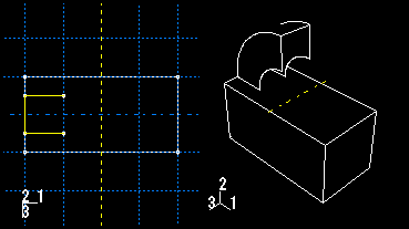
You add a revolved shell feature by sketching a profile and a construction line on a selected face. The construction line serves as an axis of revolution, and ABAQUS/CAE creates the shell feature by rotating the profile about the axis using a specified angle of revolution. A sketch and the resulting feature, rotated about the axis of revolution through an angle of 90°, are illustrated in the following figure:
To add a revolved shell feature:
From the main menu bar, select Shape![]() Shell
Shell![]() Revolve.
Revolve.
ABAQUS/CAE displays prompts in the prompt area to guide you through the procedure.
Tip:
You can also add a revolved shell feature using the ![]() tool, located with the shell tools in the Part module toolbox. For a diagram of the tools in the Part module toolbox, see “Using the Part module toolbox,” Section 11.17.
tool, located with the shell tools in the Part module toolbox. For a diagram of the tools in the Part module toolbox, see “Using the Part module toolbox,” Section 11.17.
Select the planar face from which the shell will be revolved. If no suitable face exists, you can select a datum plane.
Tip:
If you are unable to select the desired planar face, you can change the selection behavior by clicking the selection options tool ![]() in the prompt area. For more information, see “Using the selection options,” Section 6.3.
in the prompt area. For more information, see “Using the selection options,” Section 6.3.
The selected face is highlighted in the viewport.
Select an edge and the orientation of the edge on the Sketcher grid. The edge must not be perpendicular to the selected face. By default, the selected edge will appear vertical and on the right side of the Sketcher grid. To choose a different orientation for the edge, click the arrow on the right side of the dialog box and choose an orientation from the list that appears.
Tip: If the edge of the selected face is curved or does not provide the desired orientation, you can create a datum axis. You can then select the datum axis to control the orientation of the part on the Sketcher grid.
ABAQUS/CAE highlights the selected edge, enters the Sketcher, and rotates the part until the selected face aligns with the plane of the Sketcher grid and the selected edge aligns with the grid in the desired orientation.
If you are unsure of the part's orientation relative to the Sketcher grid, use the view manipulation tools from the toolbar to view its position. Use the reset view tool ![]() to return to the original view.
to return to the original view.
Use the horizontal ![]() , vertical
, vertical ![]() , angle
, angle ![]() , or oblique
, or oblique ![]() construction line tools to sketch the axis of rotation. You can position the construction line by selecting a datum axis from the underlying part. You cannot select the datum axis directly; you must select a point from either end of the datum axis.
construction line tools to sketch the axis of rotation. You can position the construction line by selecting a datum axis from the underlying part. You cannot select the datum axis directly; you must select a point from either end of the datum axis.
Use the Sketcher to sketch the two-dimensional profile of the revolved feature; the sketch must not cross the axis of revolution.
In the prompt area, click Done to indicate you have finished sketching the profile and the axis. If the sketch contains more than one construction line, ABAQUS/CAE prompts you to select the construction line that will serve as the axis of rotation.
ABAQUS/CAE displays the part view that was active prior to entering the Sketcher. The part includes your sketched profile and an arrow indicating the direction of revolution. The Edit Revolution dialog box appears.
In the Edit Revolution dialog box, enter the desired angle of revolution or accept the default value.
Click Flip next to Revolve direction to change the arrow direction and the associated direction of revolution.
If desired, toggle on Include translation, and enter a positive value for pitch. The pitch value is the distance through which the profile is translated along the axis of revolution during a rotation of 360°.
An arrow appears to show the axis of revolution and to indicate the direction of sketch translation along the axis. Click Flip next to Pitch direction in the Edit Revolution dialog box to reverse the arrow, if necessary.
If desired, toggle on Sweep sketch normal to path to rotate the sketched profile normal to the path of revolution. This option is available only when Include translation is used.
The initial profile of the feature will be rotated from the sketch plane to create the feature.
Toggle on Keep internal boundaries to maintain any faces or edges that are generated between the revolved shell feature and the existing part. The internal boundaries may create regions that can be structured or swept meshed without having to resort to partitioning.
Click OK to accept the indicated direction and to create the revolved shell feature.
ABAQUS/CAE creates the revolved feature using your selected parameters.
