
Select Shape![]() Cut
Cut![]() Extrude from the main menu bar to create an extruded cut through the part in the current viewport. The extruded cut tool is always available, regardless of the modeling space of the part in the current viewport.
Extrude from the main menu bar to create an extruded cut through the part in the current viewport. The extruded cut tool is always available, regardless of the modeling space of the part in the current viewport.
You create an extruded cut into a three-dimensional part by sketching the two-dimensional cross-section of the cut on a selected face and defining the distance through which ABAQUS/CAE extrudes the cut. You can select one of the following methods to define the distance through which the cut is extruded:
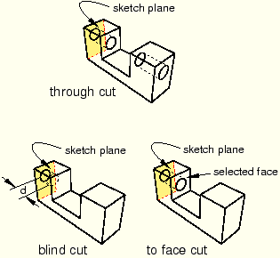
Blind extends the cut from the sketch plane in a selected direction but only to a specified depth.
Up to Face extends the cut from the sketch plane to a selected face.
Through All extends the cut from the sketch plane in a selected direction through the part.
You create an extruded cut in a two-dimensional or axisymmetric planar part by sketching the two-dimensional cross-section of the cut directly on the plane of the part. The cut always passes completely through the part.
When creating an extruded cut in a three-dimensional part, you can select a center point and specify a pitch that ABAQUS/CAE uses to twist the cross-section as it is extruded. Alternatively, ABAQUS/CAE can expand or contract the cross-section along a specified draft angle as the cross-section is extruded. For more information, see “Including twist in an extrusion,” Section 11.13.3, and “Including draft in an extrusion,” Section 11.13.4.
To create an extruded cut:
From the main menu bar, select Shape![]() Cut
Cut![]() Extrude.
Extrude.
ABAQUS/CAE displays prompts in the prompt area to guide you through the procedure.
Tip:
You can also create an extruded cut using the ![]() tool, located with the cut tools in the Part module toolbox. For a diagram of the tools in the Part module toolbox, see “Using the Part module toolbox,” Section 11.17.
tool, located with the cut tools in the Part module toolbox. For a diagram of the tools in the Part module toolbox, see “Using the Part module toolbox,” Section 11.17.
If the current viewport contains a two-dimensional or axisymmetric planar part, ABAQUS/CAE enters the Sketcher and you sketch the closed profile of the extruded cut on the plane of the part.
If the current viewport contains a three-dimensional part, you must do the following:
Select the planar face from which the cut will be extruded. If no suitable face exists, you can select a datum plane.
Tip:
If you are unable to select the desired planar face, you can change the selection behavior by clicking the selection options tool ![]() in the prompt area. For more information, see “Using the selection options,” Section 6.3.
in the prompt area. For more information, see “Using the selection options,” Section 6.3.
The selected face is highlighted in the viewport.
Select an edge and the orientation of the edge on the Sketcher grid. The edge must not be perpendicular to the selected face. By default, the selected edge will appear vertical and on the right side of the Sketcher grid. To choose a different orientation for the edge, click the arrow on the right side of the dialog box and choose an orientation from the list that appears.
Tip: If the edge of the selected face is curved or does not provide the desired orientation, you can create a datum axis. You can then select the datum axis to control the orientation of the part on the Sketcher grid.
ABAQUS/CAE highlights the selected edge, enters the Sketcher, and rotates the part until the selected face aligns with the plane of the Sketcher grid and the selected edge aligns with the grid in the desired orientation.
If you are unsure of the part's orientation relative to the Sketcher grid, use the view manipulation tools from the toolbar to view its position. Use the reset view tool ![]() to return to the original view.
to return to the original view.
Use the Sketcher to sketch the closed two-dimensional profile of the extruded cut.
In the prompt area, click Done to indicate you have finished sketching the profile.
If the current viewport contains a two-dimensional or axisymmetric planar part, the part returns to its original orientation, and ABAQUS/CAE cuts the plane with the sketched profile.
If the current viewport contains a three-dimensional part, ABAQUS/CAE displays the part in its original orientation showing the base part, your sketched profile, and an arrow indicating the extrusion direction. The Edit Cut dialog box appears. Complete the following steps to create the extruded cut in the three-dimensional part:
Click Flip in the Edit Cut dialog box to reverse the extrusion direction, if necessary.
If the arrow direction is difficult to see, use the rotate tool to rotate the part.
Select one of the following end conditions:
Select Blind and enter a value in the Depth field to specify the distance through which ABAQUS/CAE will extrude the sketched cut profile.
Select Up to Face to specify that ABAQUS/CAE will extrude the cut up to a selected face.
Select Through All to specify that ABAQUS/CAE will extrude the cut from the sketch plane completely through the part.
If desired, choose one of the following:
Select Twist and enter the pitch. The pitch is the extrusion distance in which a 360° twist would occur. The sketched cut profile must include an isolated point that indicates the center of twist.
Select Draft and enter the draft angle (greater than –90° and less than 90°). A positive draft angle indicates that external faces of the profile expand and internal faces contract.
Click OK to extrude the profile.
If you selected the twist option and your sketch includes a single isolated point, ABAQUS/CAE uses that point as the center of twist. If your sketch does not include an isolated point, ABAQUS/CAE returns to the Sketcher for you to create one. If your sketch contains more than one isolated point, ABAQUS/CAE returns to the Sketcher and prompts you to select an isolated point as the center of twist.
If you selected Up to Face, ABAQUS/CAE prompts you to select the face to which to extrude the profile. Select a face to meet the following requirements:
the selected face does not have to be parallel to the sketch plane,
it can be a nonplanar face,
it must completely contain the extruded selection, and
it cannot be a datum plane.
