You can choose to create an extrusion with draft. Draft can be used to accurately represent the small angle often applied to ease the removal of cast or molded parts from the tooling. Draft in an extrusion can also be used to create tapered parts.
In a straight extrusion the draft angle is 0°, so all extruded surfaces are perpendicular to the original profile. Draft modifies an extrusion by adjusting the angle between the extruded surfaces and the original sketch plane. ABAQUS/CAE reverses the application of draft angle from internal to external features. If external loops in a sketched profile are expanding, internal ones are contracting; this behavior is expected for draft and is required for part removal from tooling (all surfaces taper in the same direction).
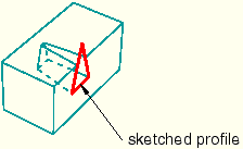
You can modify draft, along with the extrusion profile and direction, using the Feature Manipulation toolset. You can add draft during the creation of extruded solid, shell, and cut features. Figure 11–48 illustrates an extruded cut with draft in a solid part.
Note: The complete sketched profile for the cut in Figure 11–48 is a triangle, as shown. If the profile were a trapezoid whose top edge coincided with the edge of the block, the cut would look very different. As the profile was extruded, the application of draft made it smaller. The top face of a trapezoid profile would immediately fall below the surface of the block instead of extending through the top surface.
ABAQUS/CAE cannot mesh an extruded solid that includes draft with hexahedral elements unless you partition the solid into structured regions.