You can use the Part module to create complex solid revolved parts that include a translation along the axis of revolution, and you can also create solid extruded parts that include a twist about a selected center point. Free meshing allows you to mesh these parts with tetrahedral elements, as described in “Free meshing with triangular and tetrahedral elements,” Section 17.9.3. In addition, you can use hexahedral elements to mesh an extruded part that is twisted, as shown in Figure 17–100.
However, if you want to use hexahedral elements to mesh a revolved part that is translated, you will probably have to introduce partitions to make the part swept meshable, as described in the following paragraphs.For the Mesh module to create a three-dimensional swept mesh of hexahedral elements, every side that connects the source side to the target side must contain only a single face (see Figure 17–77 in “Swept meshing of three-dimensional solids,” Section 17.10.3). However, when you create a part that is revolved more than 180° and then translated along the axis of revoution, ABAQUS/CAE inserts rings along the length of the solid. These rings exist only on the surface of the part, and they do not create faces that cut through the part. As a result, the side that connects the source side and the target side now contains more than one face, and the part is not swept meshable with hexahedral elements unless you introduce partitions.
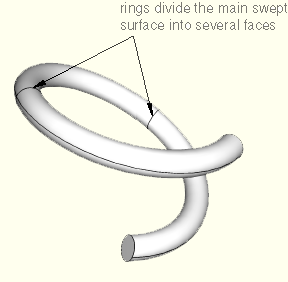
For example, Figure 17–101 shows a part that represents a coil spring. The figure also shows the rings that ABAQUS/CAE inserted when the part was created. These rings divide the connecting face between the source side and the target side; as a result, you cannot mesh an instance of the coil spring with a swept mesh of hexahedral elements until you partition the part.
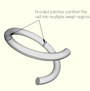
The partitioning operation introduces partitions through the solid coil using N-sided patches to define the new faces. You select the rings to define the N-sided patches, as shown in Figure 17–102.
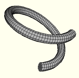
You can now seed the part instance and generate a swept mesh using hexahedral elements, as shown in Figure 17–103.