Product: ABAQUS/Standard
Slide line elements:
can model the finite-sliding interaction between two deforming bodies when the sliding occurs along a line (“slide line”) that lies in a specific plane;
assume that tangential motions orthogonal to a slide line are zero or small (ABAQUS/Standard treats such motions as being infinitesimal);
can be used with axisymmetric stress/displacement elements;
are recommended for specific applications, such as when a contact surface is the surface of a substructure or when CAXA or SAXA elements are involved in contact;
are available for first- and second-order elements; and
use the same “master-slave” concepts for enforcing contact constraints seen in surface-based contact.
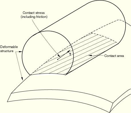
Determining the location of the areas of contact and the surface tractions between contacting structures are common goals of ABAQUS simulations (see Figure 31.4.1–1). Slide lines and slide line contact elements can provide this information for simulations where both structures are deformable and the finite sliding of the structures occurs along well-defined lines.
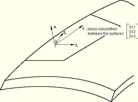
ABAQUS/Standard reports the contact stresses between the bodies and the relative motions of the bodies in a local basis system that is attached to the slide line surface. The local basis system is defined by the normal to the slide line, ![]() , and two orthogonal slip directions,
, and two orthogonal slip directions, ![]() and
and ![]() (see Figure 31.4.1–2).
(see Figure 31.4.1–2).
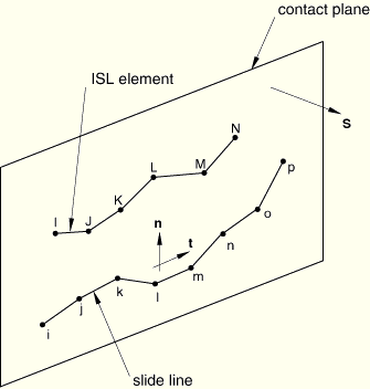
The sequence of the nodes forming the slide line defines the tangent, ![]() . The plane formed by the slide line normal,
. The plane formed by the slide line normal, ![]() , and
, and ![]() is called the contact plane. ABAQUS/Standard defines the slide line normal as
is called the contact plane. ABAQUS/Standard defines the slide line normal as ![]() (see Figure 31.4.1–3), where
(see Figure 31.4.1–3), where ![]() is the vector that is orthogonal to the contact plane.
is the vector that is orthogonal to the contact plane.
As shown in Figure 31.4.1–3, a slide line is created using nodes i, j, k, …, p, which are specified in that order, thereby identifying the slide line tangent. Nodes I, J, K, …, N are the nodes of the slide line elements that are associated with this slide line. The slide line normal ![]() is defined by specifying
is defined by specifying ![]() , the normal to the contact plane.
, the normal to the contact plane.
The tangent to the slide line coincides with the first slip direction, ![]() , of the local basis system. The second slip direction,
, of the local basis system. The second slip direction, ![]() , is in the opposite direction of
, is in the opposite direction of ![]() .
.
When creating a model that contains slide line elements, it is useful to remember that ABAQUS/Standard uses a strict “master-slave” concept to enforce the contact constraints. The slide line contact elements form the “slave” surface. The nodes that you specify to define the slide line define the “master” surface. The nodes of the slide line contact elements are constrained not to penetrate the master surface.
The considerations for choosing the master and slave surfaces are the same regardless of whether surfaces or elements are used to define contact. The master surface should be chosen as the surface of the stiffer body if the materials are different or as the surface with the coarser mesh. If the materials and mesh density are the same on both surfaces, the choice is arbitrary.
You can specify the nodes that make up the slide line, or they can be generated as described below. If you choose to specify the nodes directly, you must specify them in a sequence that defines a continuous slide line. The nodal sequence defines a tangent vector, ![]() , for the slide line. The slide line can be made up of linear or parabolic segments, depending on whether the model is made up of first-order or second-order elements. In either case convergence may be improved by smoothing the slide line.
, for the slide line. The slide line can be made up of linear or parabolic segments, depending on whether the model is made up of first-order or second-order elements. In either case convergence may be improved by smoothing the slide line.
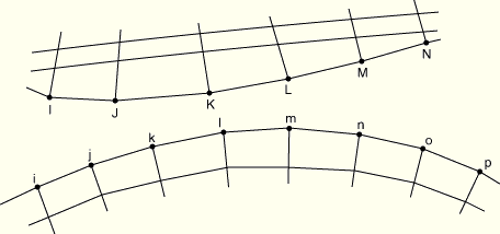
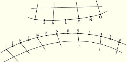
When the surfaces of the bodies are meshed with first-order elements, define a slide line made up of linear element segments. As shown in Figure 31.4.1–4), nodes i, j, k, …, p are specified in that order, thereby identifying a slide line progressing from i through p. Nodes I, J, K, …, N are the nodes of the ISL-type elements that are associated with this slide line.
| Input File Usage: | *SLIDE LINE, ELSET=element_set_name, TYPE=LINEAR first node number, second node number, etc. |
When the surfaces of the bodies are meshed with second-order elements, define a slide line made up of second-order element segments. In this case the slide line should consist of an odd number of nodes. As shown in Figure 31.4.1–5, nodes i, j, k, …, u are specified in that order, thereby identifying a slide line progressing from i through u. Nodes I, J, K, …, O are the nodes of the ISL-type elements that are associated with this slide line.
| Input File Usage: | *SLIDE LINE, ELSET=element_set_name, TYPE=PARABOLIC first node number, second node number, etc. |
Alternatively, you can indicate that the slide line nodes should be generated and specify only a first node number, a last node number, and an increment between node numbers.
| Input File Usage: | *SLIDE LINE, ELSET=element_set_name, GENERATE first node number, last node number, increment between node numbers |
Convergence is often improved by smoothing the discontinuities in surface tangents between slide line segments, thereby providing a smoothly varying tangent along the slide line. For details about smoothing slide lines, see “Contact formulation for ABAQUS/Standard contact pairs,” Section 29.2.2.
Many finite-sliding contact simulations can use the surface-based contact approach, described in Chapter 29, “Defining Contact Interactions,” to define the model. Axisymmetric stress/displacement and coupled temperature-displacement slide line elements are recommended only for specific applications, such as when a contact surface is the surface of a substructure or when CAXA or SAXA elements are involved in contact (see “Contact modeling if asymmetric-axisymmetric elements are present,” Section 29.2.10).
The slide line contact elements define the slave surface. The contact area associated with each node on the slave surface is calculated using the current length of the slide line contact element and the constant “width” assigned to the element, which depends on the underlying finite elements.
You must associate the slide line with a set of slide line contact elements. Details on defining slide lines are discussed below.
| Input File Usage: | *SLIDE LINE, ELSET=element_set_name |
You must associate the section properties with a set of slide line elements.
There are no section data for axisymmetric slide line elements.
| Input File Usage: | *INTERFACE, ELSET=element_set_name |
By default, ABAQUS/Standard uses “hard,” frictionless contact with slide line elements. You can assign optional mechanical surface interaction models. The following mechanical surface interaction models are available:
Friction. See “Frictional behavior,” Section 30.1.5, for details.
Modified “hard” contact, softened contact, and viscous damping. See “Contact pressure-overclosure relationships,” Section 30.1.2, and “Contact damping,” Section 30.1.3, for details.
When modeling contact with slide lines with axisymmetric elements (type CAX and CGAX elements), ABAQUS/Standard can calculate the maximum torque that can be transmitted across the axisymmetric slide lines. This capability is often of interest when modeling threaded connectors. The maximum torque, T, is defined as
![]()
You can request that this torque output be written to the data (.dat) file. The data are provided for every slide line in the model. You can specify the output frequency to limit how often ABAQUS/Standard writes this output to the data file. The default output frequency is 1.
For surface-based contact with axisymmetric elements, output variable CTRQ provides functionality similar to this torque output request (see “Defining contact pairs in ABAQUS/Standard,” Section 29.2.1).
| Input File Usage: | *TORQUE PRINT, FREQUENCY=n |