Products: ABAQUS/Standard ABAQUS/CAE
Contact in ABAQUS/Standard involving substructures:
is not part of the substructure definition;
requires retaining nodes on the exterior of the substructure;
requires the definition of a contact surface on the retained nodes; and
can be between the exterior of one substructure and another surface, the exterior of one substructure and the exterior of another substructure, and the exterior of one substructure and itself.
Since a substructure consists only of a group of retained nodal degrees of freedom, it has no surface geometry upon which ABAQUS/Standard can define a contact surface. One of the following methods must be used to define the surface geometry of the substructure:
mesh the exterior of the substructure with surface elements,
mesh the exterior of the substructure with structural elements,
use a node-based surface, or
use contact elements.
The surface geometry of the body being modeled with a substructure can be designated by defining elements on the retained surface nodes of the substructure. The elements can be used to create an element-based surface (see “Defining element-based surfaces,” Section 2.3.2), which can then be used as part of a contact pair.
Whenever possible, it is recommended that you use surface elements to mesh the exterior of a substructure. Surface elements will accurately define the surface geometry of the substructure without introducing any additional stiffness to the model; the stiffness of the underlying body is built into the substructure. See “Surface elements,” Section 26.7.1, for more information about surface elements.
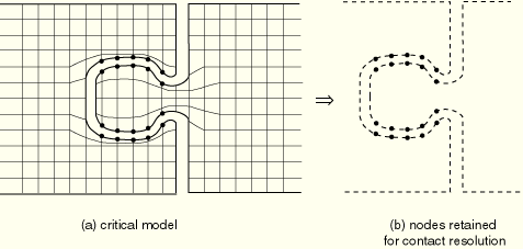
Figure 29.2.9–1 shows a simulation where both of the contacting bodies have been modeled with substructures. The nodes retained in the model are indicated in the figure. If this were a three-dimensional model, general surface elements would be used to reconstruct the appropriate surface geometries of the original mesh.
Surface elements cannot be used to overlay substructures in planar models.
Surface elements also cannot be used to overlay a substructure that consists of second-order, three-dimensional elements with midface nodes (C3D27(R)(H) or C3D15V(H)). Surface elements with midface nodes are not currently available in ABAQUS/Standard, and the 8-node surface element (SFM3D8) is not well suited for contact modeling.
Although surface elements are generally preferable for use in substructure contact situations, you can also use structural elements to define the surface geometry of a substructure. You can use membrane elements in three-dimensional models and axisymmetric models, and trusses in planar models. Define the elements to have very small thickness or area and define their material property to have a very small elastic modulus so that their contribution to the stiffness of the model is negligible.
If the model in Figure 29.2.9–1 were a planar model, truss elements would be used to connect the nodes and define the surface geometry. The truss elements would have a very small cross-sectional area and refer to a material property with very low stiffness so that they do not add any significant stiffness to the underlying bodies.
Membrane elements cannot be used to overlay a substructure that consists of second-order, three-dimensional brick elements of type C3D20(R)(H) if the substructure will be used as a slave surface. Normally, ABAQUS/Standard automatically converts C3D20(R)(H) brick elements to elements with midface nodes C3D27(R)(H) because this class of elements performs better in contact simulations. ABAQUS/Standard also converts any second-order, three-dimensional structural element that does not have a midface node when it is used in a slave surface (see “Three-dimensional surfaces with second-order faces” in “Common difficulties associated with contact modeling in ABAQUS/Standard,” Section 29.2.11, for details). Therefore, if second-order membrane elements (type M3D8) are used to reconstruct the surface topology of a substructure consisting of C3D20 elements, ABAQUS/Standard will convert them to M3D9 elements when the surface is used as a slave surface. The midface nodes that are generated automatically will not correspond to any retained nodes and, thus, will have zero stiffness. The lack of stiffness at these nodes will cause numerical problems during the analysis. Membrane elements can be used if elements of type C3D27(R)(H) have been used on the surface of the substructure.
If the retained nodes of the substructures are associated with the slave surface of a contact pair, the retained nodes can be included in a node-based surface (see “Defining node-based surfaces,” Section 2.3.3). In this case it is not necessary to overlay the surface of the substructure with elements.
GAP elements (“Gap contact elements,” Section 31.2.1) can be used to define the contact interactions in the model. These elements require that matching nodes be present on the opposite sides of the contact surfaces and allow only for small relative sliding between the surfaces. This latter assumption is usually consistent with the assumption of linear behavior that is built into a substructure.