Products: ABAQUS/Standard ABAQUS/Explicit ABAQUS/CAE
Membrane elements:
are surface elements that transmit in-plane forces only (no moments); and
have no bending stiffness.
Membrane elements are used to represent thin surfaces in space that offer strength in the plane of the element but have no bending stiffness; for example, the thin rubber sheet that forms a balloon. In addition, they are often used to represent thin stiffening components in solid structures, such as a reinforcing layer in a continuum. (If the reinforcing layer is made up of chords, rebar should be used. See “Defining rebar as an element property,” Section 2.2.4.)
In addition to the general membrane elements available in both ABAQUS/Standard and ABAQUS/Explicit, cylindrical membrane elements and axisymmetric membrane elements are available in ABAQUS/Standard only.
General membrane elements should be used in three-dimensional models in which the deformation of the structure can evolve in three dimensions.
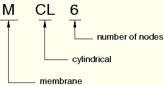
Cylindrical membrane elements are available in ABAQUS/Standard for precise modeling of regions in a structure with circular geometry, such as a tire. The elements make use of trigonometric functions to interpolate displacements along the circumferential direction and use regular isoparametric interpolation in the radial or cross-sectional plane. They use three nodes along the circumferential direction and can span a 0 to 180° segment. Elements with both first-order and second-order interpolation in the cross-sectional plane are available.
The geometry of the element is defined by specifying nodal coordinates in a global Cartesian system. The default nodal output is also provided in a global Cartesian system. Output of stress, strain, and other material point quantities is done in a corotational system that rotates with the average material rotation.
The cylindrical elements can be used in the same mesh with regular elements. In particular, regular membrane elements can be connected directly to the nodes on the cross-sectional edge of cylindrical elements. For example, any edge of an M3D4 element can share nodes with the cross-sectional edges of an MCL6 element.
Compatible cylindrical solid elements (“Cylindrical solid element library,” Section 22.1.5) and surface elements with rebar (“Surface elements,” Section 26.7.1) are available for use with cylindrical membrane elements.
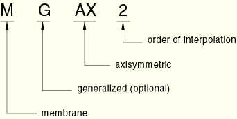
The axisymmetric membrane elements available in ABAQUS/Standard are divided into two categories: those that do not allow twist about the symmetry axis and those that do. These elements are referred to as the regular and generalized axisymmetric membrane elements, respectively.
The generalized axisymmetric membrane elements (axisymmetric membrane elements with twist) allow a circumferential component of loading or material anisotropy, which may cause twist about the symmetry axis. Both the circumferential load component and material anisotropy are independent of the circumferential coordinate ![]() . Since there is no dependence of the loading or the material on the circumferential coordinate, the deformation is axisymmetric.
. Since there is no dependence of the loading or the material on the circumferential coordinate, the deformation is axisymmetric.
The generalized axisymmetric membrane elements cannot be used in dynamic or eigenfrequency extraction procedures.
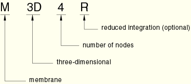
The naming convention for membrane elements depends on the element dimensionality.
General membrane elements in ABAQUS are named as follows:
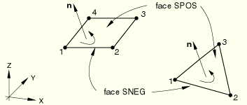
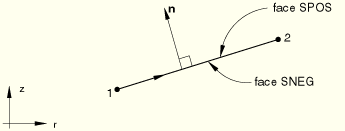
The “top” surface of a membrane is the surface in the positive normal direction (defined below) and is called the SPOS face for contact definition. The “bottom” surface is in the negative direction along the normal and is called the SNEG face for contact definition.
For general membrane elements the positive normal direction is defined by the right-hand rule going around the nodes of the element in the order that they are specified in the element definition. See Figure 23.1.1–1.
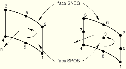
For cylindrical membrane elements the positive normal direction is defined by the right-hand rule going around the nodes of the element in the order that they are specified in the element definition. See Figure 23.1.1–2.
For axisymmetric membrane elements the positive normal is defined by a 90° counterclockwise rotation from the direction going from node 1 to node 2. See Figure 23.1.1–3.
You use a membrane section definition to define the section properties. You must associate these properties with a region of your model.
| Input File Usage: | *MEMBRANE SECTION, ELSET=name |
where the ELSET parameter refers to a set of membrane elements. |
| ABAQUS/CAE Usage: | Property module:
Create Section: select Shell as the section Category and Membrane as the
section Type
Assign |
You can define a constant section thickness as part of the section definition.
| Input File Usage: | *MEMBRANE SECTION, ELSET=name thickness |
| ABAQUS/CAE Usage: | Property module: Create Section: select Shell as the section Category and Membrane as the section Type: Membrane thickness: thickness |
Alternatively, you can define a continuously varying thickness over the element. In this case any constant section thickness you specify will be ignored, and the section thickness will be interpolated from the specified nodal values (see “Nodal thicknesses,” Section 2.1.3). The thickness must be defined at all nodes connected to the element.
| Input File Usage: | Use both of the following options: |
*MEMBRANE SECTION, NODAL THICKNESS *NODAL THICKNESS |
| ABAQUS/CAE Usage: | Continuously varying membrane thicknesses are not supported in ABAQUS/CAE. |
You must associate a material definition with each membrane section definition. Optionally, you can associate a material orientation definition with the section (see “Orientations,” Section 2.2.5). An arbitrary material orientation is valid only for general membrane elements and axisymmetric membrane elements with twist. With regular axisymmetric membrane elements it is your responsibility to ensure that either material orientation direction 1 or 2 coincides with the line of the element. The third direction should be perpendicular to the r–z plane.
| Input File Usage: | *MEMBRANE SECTION, MATERIAL=name, ORIENTATION=name |
| ABAQUS/CAE Usage: | Property module:
Create Section: select Shell as the section Category and Membrane as the
section Type: Material: name
Assign |
You can define how the membrane thickness will change with deformation by specifying a nonzero value for the section Poisson's ratio that will allow for a change in the thickness of the membrane as a function of the in-plane strains in geometrically nonlinear analysis (see “Procedures: overview,” Section 6.1.1).
Alternatively in ABAQUS/Explicit, you can choose to have the thickness change computed through integration of the thickness-direction strain that is based on the element material definition and the plane stress condition.
The value of the effective Poisson's ratio for the section must be between –1.0 and 0.5. By default, the section Poisson's ratio is 0.5 in ABAQUS/Standard to enforce incompressibility of the element; in ABAQUS/Explicit the default thickness change is based on the element material definition.
A section Poisson's ratio of 0.0 means that the thickness will not change. Values between 0.0 and 0.5 mean that the thickness changes proportionally between the limits of no thickness change and incompressibility, respectively. A negative value of the section Poisson's ratio will result in an increase of the section thickness in response to tensile strains.
| Input File Usage: | Use one of the following options: |
*MEMBRANE SECTION, POISSON= |
| ABAQUS/CAE Usage: | Property module: Create Section: select Shell as the section Category and Membrane as the section Type: Section Poisson's ratio: Use analysis default or Specify value: |
See “Methods for suppressing hourglass modes” in “Section controls,” Section 21.1.4, for more information about hourglass control.
You can specify a nondefault hourglass control formulation or scale factors for reduced-integration membrane elements. The nondefault enhanced hourglass control formulation is available only for M3D4R elements.
| Input File Usage: | Use the following option to specify a nondefault hourglass control formulation in a section control definition: |
*SECTION CONTROLS, NAME=name, HOURGLASS=hourglass_control_formulation Use the following option to associate the section control definition with the membrane section: *MEMBRANE SECTION, CONTROLS=name |
| ABAQUS/CAE Usage: | Mesh module: Mesh |
In ABAQUS/Standard you can specify nondefault hourglass stiffness factors based on the default total stiffness approach for reduced-integration general membrane elements. These stiffness factors are ignored for axisymmetric membrane elements. There are no hourglass stiffness factors or scale factors for the nondefault enhanced hourglass control formulation.
| Input File Usage: | Use both of the following options: |
*MEMBRANE SECTION *HOURGLASS STIFFNESS |
| ABAQUS/CAE Usage: | Mesh module: Mesh |
Buckling can occur in ABAQUS/Standard if a membrane structure is subject to compressive loading in a large-displacement analysis, causing out-of-plane deformation. Since a stress-free flat membrane has no stiffness perpendicular to its plane, out-of-plane loading will cause numerical singularities and convergence difficulties. Once some out-of-plane deformation has developed, the membrane will be able to resist out-of-plane loading.
In some cases loading the membrane elements in tension or adding initial tensile stress can overcome the numerical singularities and convergence difficulties associated with out-of-plane loading. However, you must choose the magnitude of the loading or initial stress such that the final solution is unaffected.