Product: ABAQUS/Standard
Line spring elements:
are used to evaluate part-through cracks (flaws) in shells inexpensively;
are used together with shell elements;
can be used with elastic or elastic-plastic (isotropic hardening, Mises yield) material behavior;
do not include thermal strain effects;
are written for small-displacement analysis only (large-rotation effects are not included);
are not available in linear perturbation steps;
use quite significant approximations (especially in the elastic-plastic case) and should, therefore, be used with care;
do not provide useful results for crack depths less than 2% or greater than 95% of the shell thickness; and
will not yield accurate results at the ends of the flaws or locations where the flaw depth varies rapidly with position, due to the three-dimensional nature of the solution in such areas.
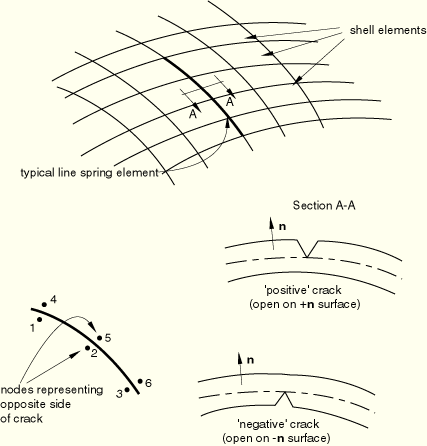
Line spring elements provide inexpensive evaluation of part-through cracks in shells. The basic concept is that these elements introduce the local solution, dominated by the singularity at the crack tip, into a shell model of the uncracked geometry. This is accomplished by allowing an additional freedom in the model along the line of the crack, this freedom being provided by the line spring elements, as indicated in Figure 26.10.1–1.
The compliance of the line spring with respect to these additional freedoms embeds the local solution in the global response. From the relative displacements and rotations conjugate to that compliance, ABAQUS/Standard computes and prints out the J-integral and, in the linear case, stress intensity factors at integration points in the line spring elements. Because the elements are simple, the analysis is not significantly more expensive than a shell analysis of the uncracked geometry. The results provide acceptable accuracy for many common applications.
See “Line spring elements,” Section 3.9.5 of the ABAQUS Theory Manual, for details of the theory behind these elements.
Two versions of the element are provided—both are intended for use with the second-order shell elements (S8R, S8R5, S9R5). Line spring element LS6 is for general cases, while line spring element LS3S is for use when the flaw lies on a symmetry plane and only one side of the symmetry plane is modeled.
You must associate the shell section properties with a set of line spring elements.
| Input File Usage: | *SHELL SECTION, ELSET=name |
You can define a constant section thickness for the line spring element as part of the shell section definition.
| Input File Usage: | *SHELL SECTION shell thickness |
Alternatively, you can define a line spring element with continuously varying thickness and specify the thickness of the line spring element at the nodes. In this case any constant section thickness you specify will be ignored, and the line spring thickness will be interpolated from the nodes (see “Nodal thicknesses,” Section 2.1.3). The thickness must be defined at all nodes connected to the element.
| Input File Usage: | Use both of the following options: |
*SHELL SECTION, NODAL THICKNESS *NODAL THICKNESS |
You must associate a material definition with each shell section definition.
Line spring elements can be used with isotropic elastic or elastic-plastic (isotropic hardening, Mises yield) material behavior (“Linear elastic behavior,” Section 17.2.1, and “Classical metal plasticity,” Section 18.2.1); these are the only material behavior definitions that are relevant to these elements. The elastic behavior must be isotropic. Plasticity is included for Mode I (crack opening) response only; an elastic-plastic analysis will be accurate only when Mode I behavior dominates.
The same material must be used through the section: a layered section cannot be defined with a line spring. Thermal strain effects are not included in the line spring elements; however, most of the thermal strain occurs in the shell, so this is not important in many cases (it is within the approximation made by line springs).
| Input File Usage: | *SHELL SECTION, ELSET=name, MATERIAL=name |
The flaw is defined by specifying its depth at each node along the crack front. You must identify whether the crack originates from the positive or negative surface of the shell (the positive surface is located a positive distance along the surface normal from the shell's middle surface, as shown in Figure 26.10.1–1).
At a point where the surface flaw depth is very small or zero, the compliance of the line spring element is also very small. To avoid numerical problems when a small compliance is inverted to form a stiffness, the minimum surface flaw depth used by ABAQUS/Standard is 2% of the thickness specified for the line spring element, even if you specify a smaller surface flaw depth. If you want to constrain the two nodes where the surface flaw depth is zero to have the same displacements, you should tie the nodes together with a linear constraint equation or a multi-point constraint (“Kinematic constraints: overview,” Section 28.1.1). This is normally not required.
| Input File Usage: | *SURFACE FLAW, SIDE=POSITIVE or NEGATIVE node number or node set label, crack depth ... |
You must specify the uncracked thickness of the shell in the section definition. The geometry of the shell at the flaw (coordinates and surface normals) is given in the usual way.
Cracks often occur on surfaces that are subjected to pressure; to include the effect of such loading on the crack faces, suitable distributed loading types are provided. These loading types are not intended for elastic-plastic line springs because the nodal equivalent forces calculated for the pressures are based on superposition methods that are valid only in the linear elastic case.
If the material is linear elastic only, the J-integral value and the stress intensity factors are output; for the elastic-plastic case local values of ![]() and
and ![]() are provided as well as their sum into a single J value. In this case the J values will have acceptable accuracy only if
are provided as well as their sum into a single J value. In this case the J values will have acceptable accuracy only if ![]() is much larger than
is much larger than ![]() . See “Line spring elements,” Section 3.9.5 of the ABAQUS Theory Manual, for further details.
. See “Line spring elements,” Section 3.9.5 of the ABAQUS Theory Manual, for further details.