Product: ABAQUS/Standard
Crack propagation analysis:
models quasi-static crack growth in two dimensions (planar and axisymmetric);
requires that you define two distinct initially bonded contact surfaces between which the crack will propagate; and
allows for three types of fracture criteria—critical stress at a certain distance ahead of the crack tip, critical crack opening displacement, and crack length versus time.
Potential crack surfaces are modeled as slave and master contact surfaces (see “Defining contact pairs in ABAQUS/Standard,” Section 29.2.1). Any contact formulation except the finite-sliding, surface-to-surface formulation can be used. The predetermined crack surfaces are assumed to be initially partially bonded so that the crack tips can be identified explicitly by ABAQUS/Standard. Initially bonded crack surfaces cannot be used with self-contact.
Define an initial condition to identify which part of the crack is initially bonded. You specify the slave surface, the master surface, and a node set that identifies the initially bonded part of the slave surface. The unbonded portion of the slave surface will behave as a regular contact surface. Either the slave surface or the master surface must be specified; if only the master surface is given, all of the slave surfaces associated with this master surface that have nodes in the node set will be bonded at these nodes.
If a node set is not specified, the initial contact conditions will apply to the entire contact pair; in this case, no crack tips can be identified, and the bonded surfaces cannot separate.
If a node set is specified, the initial conditions apply only to the slave nodes in the node set. ABAQUS/Standard checks to ensure that the node set defined includes only slave nodes belonging to the contact pair specified.
By default, the nodes in the node set are considered to be initially bonded in all directions.
| Input File Usage: | *INITIAL CONDITIONS, TYPE=CONTACT |
It is possible to bond the nodes in the node set (or the contact pair if a node set is not defined) only in the normal direction. In this case the nodes are allowed to move freely tangential to the contact surfaces. Friction (“Frictional behavior,” Section 30.1.5) cannot be specified if the nodes are bonded only in the normal direction.
Bonding only in the normal direction is typically used to model bonded contact conditions in Mode I crack problems where the shear stress ahead of the crack along the crack plane is zero.
| Input File Usage: | *INITIAL CONDITIONS, TYPE=CONTACT, NORMAL |
The crack propagation capability must be activated within the step definition to specify that crack propagation may occur between the two surfaces that are initially partially bonded. You specify the surfaces along which the crack propagates.
If the crack propagation capability is not activated for partially bonded surfaces, the surfaces will not separate; in this case the specified initial contact conditions would have the same effect as that provided by the tied contact capability, which generates a permanent bond between two surfaces during the entire analysis (see “Defining tied contact in ABAQUS/Standard,” Section 29.2.7).
| Input File Usage: | *DEBOND, SLAVE=slave_surface_name, MASTER=master_surface_name |
Cracks can propagate from either a single crack tip or multiple crack tips. The crack propagation capability in ABAQUS/Standard requires that the surfaces be initially partially bonded so that the crack tips can be identified. A contact pair can have crack propagation from multiple crack tips. However, only one crack propagation criterion is allowed for a given contact pair. Crack propagation along several contact pairs can be modeled by specifying multiple crack propagation definitions.
After debonding, the traction between two surfaces is initially carried as equal and opposite forces at the slave node and the corresponding point on the master surface. You can define how this force is to be reduced to zero with time after debonding starts at a particular node on the bonded surface. You specify a relative amplitude, a, as a function of time after debonding starts at a node. Thus, suppose the force transmitted between the surfaces at slave node N is ![]() when that node starts to debond, which occurs at time
when that node starts to debond, which occurs at time ![]() . Then, for any time
. Then, for any time ![]() the force transmitted between the surfaces at node N is
the force transmitted between the surfaces at node N is ![]() . The relative amplitude must be 1.0 at the relative time 0.0 and must reduce to 0.0 at the last relative time point given.
. The relative amplitude must be 1.0 at the relative time 0.0 and must reduce to 0.0 at the last relative time point given.
The best choice of the amplitude curve depends on the material properties, specified loading, and the crack propagation criterion. If the stresses are removed too rapidly, the resulting large changes in the strains near the crack tip can cause convergence difficulties. For large-strain problems severe mesh distortion can also occur. For problems with rate-independent materials a linear amplitude curve is normally adequate. For problems with rate-dependent materials the stresses should be ramped off more slowly at the beginning of debonding to avoid convergence and mesh distortion difficulties. Reducing the debond stress 25% in 50% of the time to debond will usually avoid problems. The solution should not be strongly influenced by the details of the unloading procedure; if it is, this usually indicates that the mesh should be refined in the debond region.
Once complete debonding has occurred at a point, the bond surfaces act like standard contact surfaces with associated interface characteristics.
You can specify the crack propagation criteria, as discussed below. Three crack propagation criteria are provided, but only one crack propagation criterion is allowed per contact pair even if multiple cracks are present.
Crack propagation analysis is carried out on a nodal basis. The crack-tip node debonds when the fracture criterion, f, reaches the value 1.0 within a given tolerance:
![]()
| Input File Usage: | *FRACTURE CRITERION, TOLERANCE= |
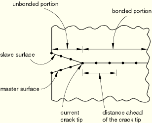
If you specify a critical stress criterion at a critical distance ahead of the crack tip, the crack-tip node debonds when the local stress across the interface at a specified distance ahead of the crack tip reaches a critical value.
This criterion is typically used for crack propagation in brittle materials. The critical stress criterion is defined as
If the value of ![]() is not given or is specified as zero, it will be taken to be a very large number so that the shear stress has no effect on the fracture criterion.
is not given or is specified as zero, it will be taken to be a very large number so that the shear stress has no effect on the fracture criterion.
The distance ahead of the crack tip is measured along the slave surface, as shown in Figure 11.4.3–1. The stresses at the specified distance ahead of the crack tip are obtained by interpolating the values at the adjacent nodes. The interpolation depends on whether first-order or second-order elements are used to define the slave surface.
| Input File Usage: | *FRACTURE CRITERION, TYPE=CRITICAL STRESS, DISTANCE=n |
If you base the crack propagation analysis on the crack opening displacement criterion, the crack-tip node debonds when the crack opening displacement at a specified distance behind the crack tip reaches a critical value. This criterion is typically used for crack propagation in ductile materials.
The crack opening displacement criterion is defined as
![]()
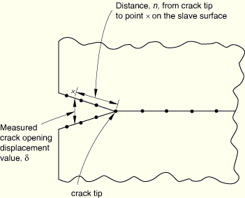
You must supply the crack opening displacement versus cumulative crack length data. In ABAQUS/Standard the cumulative crack length is defined as the distance between the initial crack tip and the current crack tip measured along the slave surface in the current configuration. The crack opening displacement is defined as the normal distance separating the two faces of the crack at the given distance.
You specify the position, n, behind the crack tip where the critical crack opening displacement is calculated. The value of this position must be specified as the length of the straight line joining the current crack tip and points on the slave and master surfaces (Figure 11.4.3–2).
ABAQUS/Standard computes the crack opening displacement at that point by interpolating the values at the adjacent nodes. The interpolation depends on whether first-order or second-order elements are used to define the slave surface. An error message will be issued if the value of n is not within the end points of the contact pair.
| Input File Usage: | *FRACTURE CRITERION, TYPE=COD, DISTANCE=n |
In problems where the debonding surfaces lie on a symmetry plane, you can specify that ABAQUS/Standard should consider only half of the user-specified crack opening displacement values. In this case the initial bonding must be in the normal direction only (see “Bonding only in the normal direction” above).
| Input File Usage: | *FRACTURE CRITERION, TYPE=COD, DISTANCE=n, SYMMETRY |
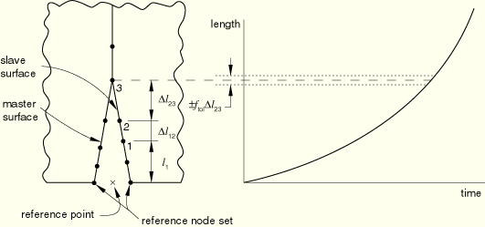
To specify the crack propagation explicitly as a function of total time, you must provide a crack length versus time relationship and a reference point from which the crack length is measured. This reference point is defined by specifying a node set. ABAQUS/Standard finds the average of the current positions of the nodes in the set to define the reference point. During crack propagation the crack length is measured from this user-specified reference point along the slave surface in the deformed configuration. The time specified must be total time, not step time.
The fracture criterion, f, is stated in terms of the user-specified crack length and the length of the current crack tip. The length of the current crack tip from the reference point is measured as the sum of the straight line distance of the initial crack tip from the reference point and the distance between the initial crack tip and the current crack tip measured along the slave surface.
Referring to Figure 11.4.3–3, let node 1 be the initial location of the crack tip and node 3 be the current location of the crack tip. The distance of the current crack tip located at node 3 is given by
![]()
![]()
If geometric nonlinearity is considered in the step (“Procedures: overview,” Section 6.1.1), the reference point may move as the body deforms; you must ensure that this movement does not invalidate the crack length versus time criterion.
ABAQUS/Standard does not extrapolate beyond the end points of your crack data. Therefore, if the first crack length specified is greater than the distance from the crack reference point to the first bonded node, the first bonded node will never debond and the crack will not propagate. In this case ABAQUS/Standard will print warning messages in the message (.msg) file.
| Input File Usage: | *FRACTURE CRITERION, TYPE=CRACK LENGTH, NSET=name |
Crack propagation analysis can be performed using the following procedures:
When automatic incrementation is used, you can specify the size of the time increment used just after debonding starts. By default, the time increment is equal to the last relative time specified. However, if a fracture criterion is met at the beginning of an increment, the size of the time increment used just after debonding starts will be set equal to the minimum time increment allowed in this step.
For fixed time incrementation the specified time increment value will be used as the time increment size after debonding starts if ABAQUS/Standard finds it needs a smaller time increment than the fixed time increment size. The time increment size will be modified as required until debonding is complete.
| Input File Usage: | *DEBOND, SLAVE=slave, MASTER=master, TIME INCREMENT=t |
Initial contact conditions are used to identify which part of the slave surface is initially bonded, as explained earlier.
Boundary conditions should not be applied to any of the nodes on the master or slave crack surfaces, but they can be used to load the structure and cause crack propagation. Boundary conditions can be applied to any of the displacement degrees of freedom in a crack propagation analysis (“Boundary conditions,” Section 27.3.1).
The following types of loading can be prescribed in a crack propagation analysis:
Concentrated nodal forces can be applied to the displacement degrees of freedom (1–6); see “Concentrated loads,” Section 27.4.2.
Distributed pressure forces or body forces can be applied; see “Distributed loads,” Section 27.4.3. The distributed load types available with particular elements are described in Part VI, “Elements.”
The following predefined fields can be specified in a crack propagation analysis, as described in “Predefined fields,” Section 27.6.1:
Although temperature is not a degree of freedom in stress/displacement elements, nodal temperatures can be specified as predefined fields. The specified temperature affects temperature-dependent critical stress and crack opening displacement failure criteria, if specified.
The values of user-defined field variables can be specified. These values affect field-variable-dependent critical stress and crack opening displacement failure criteria, if specified.
Any of the mechanical constitutive models in ABAQUS/Standard can be used to model the mechanical behavior of the cracking material. See Part V, “Materials.”
Regular, rectangular meshes give the best results in crack propagation analyses. Results with nonlinear materials are more sensitive to meshing than results with small-strain linear elasticity.
First-order elements (CPE4, CAX4, etc.) generally work best for crack propagation analysis.
Line spring elements cannot be used in crack propagation analysis.
At the start of an analysis ABAQUS/Standard will scan the partially bonded surfaces and identify all of the crack tips that are present in the model. The initial contact status of all of the slave surface nodes is printed in the data (.dat) file. At this stage ABAQUS/Standard will explicitly identify all the crack tips and mark them as crack 1, crack 2, etc. The slave and master surfaces that are associated with these cracks are also identified.
By default, crack propagation information will be printed to the data file during the analysis. For each crack that is identified ABAQUS/Standard will print out the initial and current crack-tip node numbers, accumulated incremental crack length (distance from the initial crack tip to the current crack tip, measured along the slave surface), and the current value of the user-specified fracture criterion used.
| Input File Usage: | *DEBOND, SLAVE=slave, MASTER=master |
For example, if the crack opening displacement criterion is used, the printed output during the analysis will appear as follows in the data file:
     CRACK TIP LOCATION AND ASSOCIATED QUANTITIES
CRACK  SLAVE   MASTER  INITIAL  CURRENT  CUMULATIVE  CRITICAL
NUMBER SURFACE SURFACE CRACKTIP CRACKTIP INCREMENTAL COD
                       NODE #   NODE #   LENGTH

You can choose to write the crack propagation information to the results (.fil) file.
| Input File Usage: | *DEBOND, SLAVE=slave, MASTER=master, OUTPUT=FILE |
You can write the crack propagation information to both the data and the results files.
| Input File Usage: | *DEBOND, SLAVE=slave, MASTER=master, OUTPUT=BOTH |
You can control the output frequency in increments. By default, the crack-tip location and associated quantities will be printed every increment. Specify an output frequency of 0 to suppress crack propagation output.
| Input File Usage: | *DEBOND, SLAVE=slave, MASTER=master, FREQUENCY=f |
The following bond failure quantities can be requested as surface output (see “Output to the data and results files,” Section 4.1.2):
DBT | The time when bond failure occurred. |
DBSF | Fraction of stress at bond failure that still remains. |
DBS | All components of remaining stress in the failed bond. |
DBS1i | 1i component of stress in the failed bond that remains ( |
ABAQUS/CAE provides support for the visualization of time-history plots and X–Y plots of the variables that are written to the output database.
Contour integrals can be requested for two-dimensional crack propagation analysis. If the contours are chosen so that the crack tip passes through the contour, the contour value will go to zero (as it should). Therefore, in crack propagation analysis contour integrals should be requested far enough from the crack tip that the crack tip does not pass through the contour, which is easily done by including all nodes along the bond surface in the crack-tip node set specified. See “Contour integral evaluation,” Section 11.4.2, for details on contour integral output.
*HEADING
…
*BOUNDARY
Data lines to specify zero-valued boundary conditions
*INITIAL CONDITIONS, TYPE=CONTACT (, NORMAL)
Data lines to specify initial conditions
*SURFACE, NAME=slave
Data lines to define slave surface
*SURFACE, NAME=master
Data lines to define master surface
*CONTACT PAIR
slave, master
**
*STEP (, NLGEOM)
*STATIC or *VISCO or *COUPLED TEMPERATURE-DISPLACEMENT
*DEBOND, SLAVE=slave, MASTER=master
Data lines to define debonding amplitude curve
*FRACTURE CRITERION, TYPE=type, DISTANCE or NSET
Data lines to define fracture criterion
*BOUNDARY
Data lines to define zero-valued or nonzero boundary conditions
*CLOAD and/or *DLOAD and/or *TEMPERATURE and/or *FIELD
Data lines to define loading
**
*CONTOUR INTEGRAL, CONTOURS=n, TYPE=type
**Contour integrals can be requested in a two-dimensional crack propagation analysis
*CONTACT PRINT
DBT, DBSF, DBS
*EL PRINT
JK,
*END STEP