To create a solid feature, select Shape![]() Solid from the main menu bar or select one of the solid tools in the Part module toolbox. Once you have sketched the initial profile, you perform one of the following operations to create the feature:
Solid from the main menu bar or select one of the solid tools in the Part module toolbox. Once you have sketched the initial profile, you perform one of the following operations to create the feature:
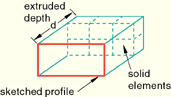
To create an extruded solid feature, you extrude the profile through a specified distance (d), as shown in Figure 11–15.
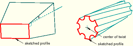
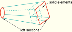
In addition, you can apply either draft or twist to the extrusion, as shown in Figure 11–16. You define the draft angle for an extrusion with draft or the center of twist and the pitch (the extrusion distance in which a 360° twist occurs) for an extrusion with twist. Select ShapeTo create a solid loft feature, you transition the shape from the initial loft section to an end section of a different shape or orientation. ABAQUS/CAE determines the shape between the start and end sections using tangency constraints, intermediate sections, and a path curve. A simple loft (with only two loft sections, no tangency constraints, and a straight path) is shown in Figure 11–17. Select Shape![]() Solid
Solid![]() Loft from the main menu bar to create this type of feature.
Loft from the main menu bar to create this type of feature.
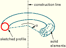
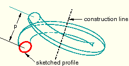
To create a revolved solid feature, you revolve the profile through a specified angle (![]() ). A construction line serves as the axis of revolution, as shown in Figure 11–18.
). A construction line serves as the axis of revolution, as shown in Figure 11–18.
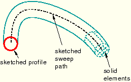
To create a swept solid feature, you sweep the profile along a specified path, as shown in Figure 11–20. Select Shape![]() Solid
Solid![]() Sweep from the main menu bar to create this type of feature. For more information, see “Defining the sweep path and the sweep profile,” Section 11.13.8.
Sweep from the main menu bar to create this type of feature. For more information, see “Defining the sweep path and the sweep profile,” Section 11.13.8.
You can use any of the solid tools to add a solid feature to a deformable or discrete part that you created in three-dimensional modeling space. You cannot add a solid feature to a two-dimensional or axisymmetric part.
Figure 11–15, Figure 11–17, Figure 11–18, and Figure 11–20 illustrate how each feature might later be meshed. You can mesh a solid feature using any of the three-dimensional, solid continuum elements available in ABAQUS/Standard or ABAQUS/Explicit.