To create a swept feature, select Shape![]() Solid
Solid![]() Sweep, Shape
Sweep, Shape![]() Shell
Shell![]() Sweep, or Shape
Sweep, or Shape![]() Cut
Cut![]() Sweep from the main menu bar or select the equivalent tool from the Part module toolbox.
Sweep from the main menu bar or select the equivalent tool from the Part module toolbox.
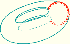
Sweeping is a two-part operation: first you sketch the sweep path, and then you sketch the sweep profile. The profile is swept along the length of the path to form a three-dimensional solid, shell, or cut feature. The sweep path can be any continuous path you can create with the Sketcher. The beginning of the path is always perpendicular to the sweep profile, and the profile always remains normal to the path as it is swept along its length. Figure 11–49 shows an example of a sweep path and a sweep profile.
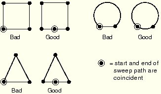
The feature created by sweeping the sweep profile along the above path is shown in Figure 11–50. The sketches that define the sweep path and the sweep profile can both be modified using the Feature Manipulation toolset. The sweeping tools are available only when you are working on a deformable or discrete part that you created in a three-dimensional modeling space.The sweep profile must be closed when you are creating a swept solid or cut feature. However, unlike the sweep profile, the sweep path can be open or closed regardless of whether you are creating a swept solid, shell, or cut feature. If the sweep path is closed, the two ends of the path must meet tangentially. For example, the closed sweep paths labeled “Bad” in Figure 11–51 are not allowed because the ends of the path meet at an angle.