Product: ABAQUS/Standard
Tube-to-tube elements:
model the finite-sliding interaction between two pipelines or tubes where one tube lies inside the other or between two tubes or rods that lie next to each other;
are slide line contact elements, in the sense that they assume that the relative motion of the two tubes or pipes is predominantly along the line defined by the axis of one of the tubes (the relative rotations of the tube or pipe axis are assumed to be small);
can be used with pipe, beam, or truss elements; and
do not consider deformations of the tube or pipe cross-section.
The tube-to-tube contact elements can be used to model two specific classes of tube-to-tube contact problems: internal (tube within a tube) contact and external contact, where the two tubes are roughly parallel and contact each other along their outer surfaces. It is not possible to use the surface-based contact approach for problems where two three-dimensional tubes contact each other.
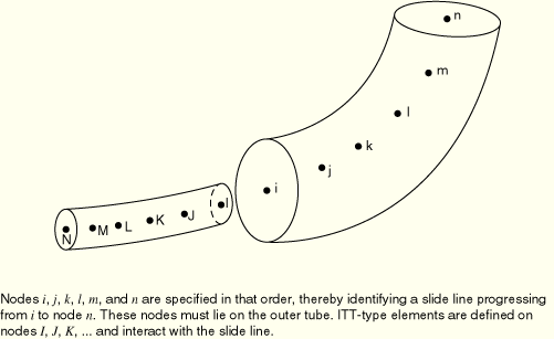
Use ITT21 elements with two-dimensional beam, pipe, or truss elements. Use ITT31 elements with three-dimensional beam, pipe, or truss elements. Each of these elements is defined by a single node.
You must indicate which set of tube-to-tube contact elements will interact with a particular slide line. Details on defining slide lines are discussed below.
| Input File Usage: | *SLIDE LINE, ELSET=element_set_name |
You must associate the geometric section properties with a set of tube-to-tube contact elements.
| Input File Usage: | *INTERFACE, ELSET=element_set_name |
You define the radial clearance between the pipes. Give a positive value to model contact between two pipes when one pipe (the one with the tube-to-tube contact elements) lies inside of the other pipe. The value given is the difference between the inner radius of the outer pipe and the outer radius of the inner pipe.
| Input File Usage: | *INTERFACE radial clearance |
The element output variables for ITT elements are given in a local basis system associated with the slide line. The first tangent vector, ![]() , is defined by the sequence of the nodes forming the slide line. The direction of contact,
, is defined by the sequence of the nodes forming the slide line. The direction of contact, ![]() , is the normal to the slide line that points toward the nodes of the ITT elements. For ITT31 elements ABAQUS/Standard forms a second tangent vector,
, is the normal to the slide line that points toward the nodes of the ITT elements. For ITT31 elements ABAQUS/Standard forms a second tangent vector, ![]() , that is orthogonal to both
, that is orthogonal to both ![]() and
and ![]() . As the elements move, the local basis system will rotate with the axis of the slide line.
. As the elements move, the local basis system will rotate with the axis of the slide line.
In the case of internal tube-to-tube contact, the slide line can be placed on the inner tube or the outer tube. Generally the slide line should be associated with the outer tube (see Figure 31.3.1–1); however, if the inner tube is stiffer than the outer tube, the slide line should be attached to the inner tube.
If contact occurs between the exterior surface of the tubes, the slide line should be associated with the stiffer tube if the materials or tube radii are different or with the tube with the coarser mesh if they are the same.
You can specify the nodes that make up the slide line, or they can be generated as described below. If you choose to specify the nodes directly, you must specify them in a sequence that defines a continuous slide line. The nodal sequence defines a tangent vector ![]() for the slide line. The slide line must be made up of linear segments.
for the slide line. The slide line must be made up of linear segments.
| Input File Usage: | *SLIDE LINE, ELSET=element_set_name, TYPE=LINEAR first node number, second node number, etc. |
Alternatively, you can indicate that the slide line nodes should be generated and specify only a first node number, a last node number, and an increment between node numbers.
| Input File Usage: | *SLIDE LINE, GENERATE first node number, last node number, increment between node numbers |
Convergence is often improved by smoothing the discontinuities in surface tangents between slide line segments, thereby providing a smoothly varying tangent along the slide line. For details about smoothing slide lines, see “Contact formulation for ABAQUS/Standard contact pairs,” Section 29.2.2.
By default, ABAQUS/Standard uses “hard,” frictionless contact with tube-to-tube contact elements. You can assign optional mechanical surface interaction models. The following mechanical surface interaction models are available:
Friction. See “Frictional behavior,” Section 30.1.5, for details.
Modified “hard” contact, softened contact, and viscous damping. See “Contact pressure-overclosure relationships,” Section 30.1.2, and “Contact damping,” Section 30.1.3, for details.