Products: ABAQUS/Standard ABAQUS/Explicit ABAQUS/CAE
Dashpot-like connector damping behavior:
can be defined in any connector with available components of relative motion;
can be specified for each available component of relative motion independently, in which case the behavior can be linear or nonlinear;
can be specified as dependent on relative positions or constitutive motions in several local directions; and
can be specified for all available components of relative motion as coupled damping behavior.
In the simplest case of linear uncoupled damping you define the damping coefficients for the selected components (i.e., ![]() for component 1,
for component 1, ![]() for component 2, etc.), which are used in the equation
for component 2, etc.), which are used in the equation
![]()
| Input File Usage: | Use the following options to define linear uncoupled damping connector behavior: |
*CONNECTOR BEHAVIOR, NAME=name *CONNECTOR DAMPING, COMPONENT=component number, DEPENDENCIES=n |
| ABAQUS/CAE Usage: | Interaction module: connector section editor: Add |
In the linear coupled case you define the damping coefficient matrix components, ![]() , which are used in the equation
, which are used in the equation
![]()
| Input File Usage: | Use the following options to define linear coupled damping connector behavior: |
*CONNECTOR BEHAVIOR, NAME=name *CONNECTOR DAMPING, DEPENDENCIES=n |
| ABAQUS/CAE Usage: | Interaction module: connector section editor: Add |
For nonlinear damping you specify forces or moments as nonlinear functions of the velocity in the available components of relative motion directions, ![]() . These functions can also depend on temperature and field variables. See “Input syntax rules,” Section 1.2.1, for further information about defining data as functions of temperature and field variables.
. These functions can also depend on temperature and field variables. See “Input syntax rules,” Section 1.2.1, for further information about defining data as functions of temperature and field variables.
By default, each nonlinear force or moment function is dependent only on the velocity in the direction of the specified component of relative motion.
| Input File Usage: | Use the following options: |
*CONNECTOR BEHAVIOR, NAME=name *CONNECTOR DAMPING, COMPONENT=component number, NONLINEAR, DEPENDENCIES=n |
| ABAQUS/CAE Usage: | Interaction module: connector section editor: Add |
Alternatively, the functions can depend on the relative positions or constitutive displacements/rotations in several component directions, as described in “Defining nonlinear connector behavior properties to depend on relative positions or constitutive displacements/rotations” in “Connector behavior,” Section 25.2.1.
| Input File Usage: | Use the following options to define nonlinear damping connector behavior that depends on components of relative position: |
*CONNECTOR BEHAVIOR, NAME=name
*CONNECTOR DAMPING, COMPONENT=component number,
NONLINEAR, INDEPENDENT COMPONENTS=POSITION,
DEPENDENCIES=n
Use the following options to define nonlinear damping connector behavior that depends on components of constitutive displacements or rotations: *CONNECTOR BEHAVIOR, NAME=name *CONNECTOR DAMPING, COMPONENT=component number, NONLINEAR, INDEPENDENT COMPONENTS=CONSTITUTIVE MOTION, DEPENDENCIES=n |
| ABAQUS/CAE Usage: | Interaction module: connector section editor: Add |
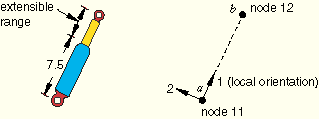
Refer to the example in Figure 25.2.3–1.
In addition to the torsional spring resisting relative rotations, the shock absorber damps translational motion along the line of the shock with a dashpot. To include a nonlinear dashpot behavior that is dependent on the relative position between the attachment points, use the following input:*CONNECTOR BEHAVIOR, NAME=sbehavior ... *CONNECTOR DAMPING, COMPONENT=1, INDEPENDENT COMPONENTS=POSITION, NONLINEAR 1 1500.0, 0.1, 0.0 1625.0, 0.2, 0.0 1750.0, 0.1, 10.0 1925.0, 0.2, 10.0
In direct-solution or subspace-based steady-state dynamic procedures, the damping defined using an uncoupled connector damping behavior may be frequency dependent. In all other linear perturbation procedures connector damping behavior is ignored.
The ABAQUS output variables available for connectors are listed in “ABAQUS/Standard output variable identifiers,” Section 4.2.1, and “ABAQUS/Explicit output variable identifiers,” Section 4.2.2. The following output variables are of particular interest when defining damping in connectors:
CV | Connector relative velocities/angular velocities. |
CVF | Connector viscous forces/moments. |