Products: ABAQUS/Standard ABAQUS/Explicit ABAQUS/CAE
“Specifying connector derived components,” Section 15.15.14 of the ABAQUS/CAE User's Manual, in the online HTML version of this manual
“Specifying potential terms,” Section 15.15.15 of the ABAQUS/CAE User's Manual, in the online HTML version of this manual
This section describes how to define two special functions used to specify complex coupled behavior for a connector element in ABAQUS: derived components and potentials.
Connector derived components are user-specified component definitions based on a function of intrinsic (1 through 6) connector components of relative motion. They can be used:
to specify the friction-generating normal force in connectors as a complex combination of connector forces and moments, and
as an intermediate result in a connector potential function.
the yield function for connector coupled plasticity when several available components of relative motion are involved simultaneously,
the potential function for coupled user-defined friction when the slip direction is not aligned with an available component of relative motion,
a magnitude measure as a coupled function of connector forces or motions used to detect the initiation of damage in the connector, and
an effective motion measure as a coupled function of connector motions to drive damage evolution in the connector.
The definition of coupled behavior in connector elements beyond simple linear elasticity or damping often requires the definition of a resultant force involving several intrinsic (1 through 6) components or the definition of a “direction” not aligned with any of the intrinsic components. These user-defined resultants or directions are called derived components. The forces and motions associated with these derived components are functions of the forces and motions in the intrinsic relative components of motion in the connector element.
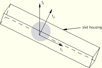
Consider the case of a SLOT connector for which frictional effects (see “Connector friction behavior,” Section 25.2.5) are defined in the only available component of relative motion (the 1-direction). The two constraints enforced by this connection type will produce two reaction forces (![]() and
and ![]() ), as shown in Figure 25.2.4–1. Both forces generate friction in the 1-direction in a coupled fashion.
), as shown in Figure 25.2.4–1. Both forces generate friction in the 1-direction in a coupled fashion.
![]()
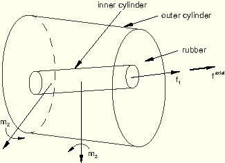
Resultant forces that can be defined as derived components may take more complicated forms. Consider a BUSHING connection type for which a tensile (Mode I) damage mechanism with failure is to be specified in the 1-direction. You may wish to include the effects of the axial force ![]() and of the resultant of the “flexural” moments
and of the resultant of the “flexural” moments ![]() and
and ![]() in defining an overall resultant force in the axial direction upon which damage initiation (and failure) can be triggered, as shown in Figure 25.2.4–2.
in defining an overall resultant force in the axial direction upon which damage initiation (and failure) can be triggered, as shown in Figure 25.2.4–2.
![]()
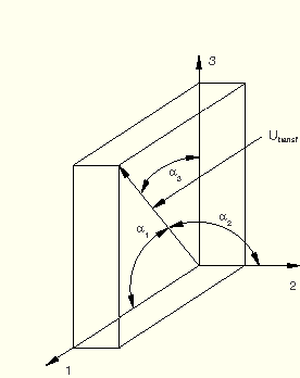
A derived component can also be interpreted as a user-specified direction that is not aligned with the connector component directions. For example, if the motion-based damage with failure criterion in a CARTESIAN connection with elastic behavior does not align with the intrinsic component directions, the damage criterion can be defined in terms of a derived component representing a different direction, as shown in Figure 25.2.4–3.
One possible choice for the direction could be![]()
The functional form of a derived component ![]() in ABAQUS is quite general; you specify its exact form. The derived component is specified as a sum of terms
in ABAQUS is quite general; you specify its exact form. The derived component is specified as a sum of terms
a norm
a direct sum
Connector derived components are identified by the names given to them. If one term (![]() ) is sufficient to define the derived component g, specify only one connector derived component definition.
) is sufficient to define the derived component g, specify only one connector derived component definition.
| Input File Usage: | *CONNECTOR DERIVED COMPONENT, NAME=derived_component_name |
| ABAQUS/CAE Usage: | Connector derived component names are not supported in ABAQUS/CAE; you define the individual derived component terms. |
Use the following input to define a connector derived component term for a friction-generating user-defined contact force: Interaction module: connector section editor: Add Use the following input to define a connector derived component term as an intermediate result in a connector potential function: Interaction module: connector section editor: Add |
If several terms (![]() ,
, ![]() , etc.) are needed in the overall definition of the derived component g, you must define the individual terms.
, etc.) are needed in the overall definition of the derived component g, you must define the individual terms.
| Input File Usage: | You must specify |
*CONNECTOR DERIVED COMPONENT, NAME=derived_component_name *CONNECTOR DERIVED COMPONENT, NAME=derived_component_name ... |
| ABAQUS/CAE Usage: | Connector derived component names are not supported in ABAQUS/CAE; you define the individual derived component terms. |
Interaction module: derived component editor: click Add and select components. Repeat, adding terms as necessary. |
By default, a derived component term is computed as the square root of the sum of the squares of each intrinsic component contribution. If the term has only one contribution (![]() ), the norm has the same meaning as the absolute value.
), the norm has the same meaning as the absolute value.
| Input File Usage: | *CONNECTOR DERIVED COMPONENT, NAME=derived_component_name, OPERATOR=NORM (default) |
For example, the following input can be used to define the *CONNECTOR DERIVED COMPONENT, NAME=axial 1 1.0, ** The axial derived component is |
| ABAQUS/CAE Usage: | Interaction module: derived component editor: Add: Term operator: Square root of sum of squares |
Alternatively, you can choose to compute a derived component term as the direct sum of the intrinsic component contributions.
| Input File Usage: | *CONNECTOR DERIVED COMPONENT, NAME=derived_component_name, OPERATOR=SUM |
For example, the following input can be used to define the *CONNECTOR DERIVED COMPONENT, NAME=transf, OPERATOR=SUM 1, 2, 3 The transf derived component is |
| ABAQUS/CAE Usage: | Interaction module: derived component editor: Add: Term operator: Sum |
You can specify whether the sign of a derived component term should be positive or negative.
| Input File Usage: | Use one of the following options: |
*CONNECTOR DERIVED COMPONENT, NAME=derived_component_name, SIGN=POSITIVE (default) *CONNECTOR DERIVED COMPONENT, NAME=derived_component_name, SIGN=NEGATIVE |
| ABAQUS/CAE Usage: | Interaction module: derived component editor: Add: Overall term sign: Positive or Negative |
The scaling factors ![]() used in the definition of the derived component can depend on the relative positions or constitutive displacements/rotations in several component directions, as described in “Defining nonlinear connector behavior properties to depend on relative positions or constitutive displacements/rotations” in “Connector behavior,” Section 25.2.1. See the first example in “Connector friction behavior,” Section 25.2.5, for an illustration.
used in the definition of the derived component can depend on the relative positions or constitutive displacements/rotations in several component directions, as described in “Defining nonlinear connector behavior properties to depend on relative positions or constitutive displacements/rotations” in “Connector behavior,” Section 25.2.1. See the first example in “Connector friction behavior,” Section 25.2.5, for an illustration.
| Input File Usage: | Use the following option to define a connector derived component that depends on components of relative position: |
*CONNECTOR DERIVED COMPONENT,
INDEPENDENT COMPONENTS=POSITION
Use the following option to define a connector derived component that depends on components of constitutive displacements or rotations: *CONNECTOR DERIVED COMPONENT, INDEPENDENT COMPONENTS=CONSTITUTIVE MOTION |
| ABAQUS/CAE Usage: | Interaction module: derived component editor: Add: Use local directions: Independent position components or Independent constitutive motion components |
When a derived component is used to construct the yield function for a plasticity or friction definition, the following simple requirements must be satisfied:
All ![]() terms of a derived component must be of the same type (see “Functional form of the derived component”); norm-type terms (
terms of a derived component must be of the same type (see “Functional form of the derived component”); norm-type terms (![]() -type) cannot be mixed with direct sum-type terms (
-type) cannot be mixed with direct sum-type terms (![]() -type) in the same derived component definition.
-type) in the same derived component definition.
If all ![]() terms are norm-type terms, the sign of each term must be positive (the default).
terms are norm-type terms, the sign of each term must be positive (the default).
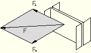
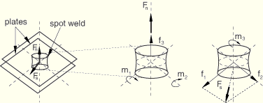
The spot weld shown in Figure 25.2.4–4 is subjected to loading in the F-direction.
The connector chosen to model the spot weld has six available components of relative motion: three translations (components 1–3) and three rotations (components 4–6). You have chosen this connection type because you are modeling a general deformation state. However, you would like to define inelastic behavior in the connection in terms of a normal and a shear force since experimental data are available in this format. Therefore, you want to derive the normal and shear components of the force, for example, as follows:![]()
![]()
To define ![]() , you would specify the following two connector derived component definitions, each with the same name:
, you would specify the following two connector derived component definitions, each with the same name:
*PARAMETERThe=12.27 A=19.63
=sqrt(
)
=


*CONNECTOR DERIVED COMPONENT, NAME=normal 3 1.0 *CONNECTOR DERIVED COMPONENT, NAME=normal 4, 5
,
Similarly, to define ![]() , you would specify the following two connector derived component definitions for the component shear:
, you would specify the following two connector derived component definitions for the component shear:
*CONNECTOR DERIVED COMPONENT, NAME=shear 6*CONNECTOR DERIVED COMPONENT, NAME=shear 1, 2 1.0, 1.0
Connector potentials are user-defined mathematical functions that represent yield surfaces, limiting surfaces, or magnitude measures in the space spanned by the components of relative motion in the connector. The functions can be quadratic, general elliptical, or maximum norms. The connector potential does not define a connector behavior by itself; instead, it is used to define the following coupled connector behaviors:
friction,
plasticity, or
damage.
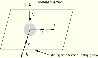
Consider the case of a SLIDE-PLANE connection in which frictional sliding occurs in the connection plane, as shown in Figure 25.2.4–6.
The function governing the stick-slip frictional behavior (see “Connector friction behavior,” Section 25.2.5) can be written as![]()
![]()
Connector potentials can also be useful in defining connector damage with a force-based coupled damage initiation criterion. For example, in a connection type with six available components of relative motion you could define a potential
Connector potentials can take more complicated forms. Assume that coupled plasticity is to be defined in a spot weld, in which case a plastic yield criterion can be defined as
![]()
![]()
| Input File Usage: | *CONNECTOR POTENTIAL |
| ABAQUS/CAE Usage: | Use the following input to define connector potentials for friction behavior: |
Interaction module: connector section editor: Add Use the following input to define connector potentials for plasticity behavior: Interaction module: connector section editor: Add Use the following input to define connector potentials for damage behavior: Interaction module: connector section editor: Add |
The functional form of the potential ![]() in ABAQUS is quite general; you specify its exact form. The potential is specified as one of the following direct functions of several contributions:
in ABAQUS is quite general; you specify its exact form. The potential is specified as one of the following direct functions of several contributions:
a quadratic form
a general elliptical form
a maximum form
![]()
![]() is a direct function of either an intrinsic connector component (1 through 6) or a derived connector component. Since derived components are ultimately a function of intrinsic components (see “Defining derived components for connector elements”), the contribution
is a direct function of either an intrinsic connector component (1 through 6) or a derived connector component. Since derived components are ultimately a function of intrinsic components (see “Defining derived components for connector elements”), the contribution ![]() is ultimately a function of
is ultimately a function of ![]() .
. ![]() is defined as
is defined as
![]()
![]()
![]()
is the function used to generate the contribution:
absolute value (default, ![]() ),
),
Macauley bracket (![]() ), or
), or
identity (X);
![]()
is the value of the identified component (intrinsic or derived);
![]()
is a shift factor (default 0.0); and
![]()
is a scaling factor (default 1.0).
To define a general elliptical form of the potential, you must specify the inverse of the overall exponent, ![]() . You can also define the exponents
. You can also define the exponents ![]() if they are different from the default value, which is the specified value of
if they are different from the default value, which is the specified value of ![]() .
.
| Input File Usage: | To define a quadratic form of the potential, you can omit specifying |
*CONNECTOR POTENTIAL component name or number, Use the following option to define a general elliptical form of the potential: *CONNECTOR POTENTIAL, OPERATOR=SUM, EXPONENT= Each data line defines one contribution to the potential, |
| ABAQUS/CAE Usage: | Interaction module: connector section editor: friction, plasticity, or damage behavior option: Force Potential, Initiation Potential, or Evolution Potential: Operator: Sum, Exponent: 2 (for quadratic form) or |
Alternatively, you can define the potential as a maximum form.
| Input File Usage: | *CONNECTOR POTENTIAL, OPERATOR=MAX component name or number, |
Each data line defines one contribution to the potential, |
| ABAQUS/CAE Usage: | Interaction module: connector section editor: friction, plasticity, or damage behavior option: Force Potential, Initiation Potential, or Evolution Potential: Operator: Maximum, select Add and enter data for the potential contribution. Repeat, adding contributions as necessary. |
The connector potential, ![]() , can be defined using intrinsic components of relative motion, derived components, or both. A particular contribution to the potential may be one of the following two types:
, can be defined using intrinsic components of relative motion, derived components, or both. A particular contribution to the potential may be one of the following two types:
A norm-type contribution (![]() ) defined using the absolute value or the Macauley bracket functions or using a norm-type derived component,
) defined using the absolute value or the Macauley bracket functions or using a norm-type derived component, ![]() (see “Requirements for constructing a derived component used in plasticity or friction definitions”) with any of the available functions.
(see “Requirements for constructing a derived component used in plasticity or friction definitions”) with any of the available functions.
A sum-type contribution (![]() ) defined using an intrinsic component of relative motion or a derived component of type
) defined using an intrinsic component of relative motion or a derived component of type ![]() (see “Requirements for constructing a derived component used in plasticity or friction definitions”) together with the identity function.
(see “Requirements for constructing a derived component used in plasticity or friction definitions”) together with the identity function.
All ![]() contributions to the potential must be of the same type. Mixed
contributions to the potential must be of the same type. Mixed ![]() and
and ![]() contributions are not allowed in the same potential definition.
contributions are not allowed in the same potential definition.
If all ![]() terms are
terms are ![]() -type terms, the sign of each term must be positive (the default).
-type terms, the sign of each term must be positive (the default).
The positive numbers ![]() and
and ![]() cannot be smaller than 1.0 and must be equal (the default).
cannot be smaller than 1.0 and must be equal (the default).
Referring to the spot weld shown in Figure 25.2.4–5 and the yield function ![]() defined above, you would define this potential using the derived components normal and shear with the following input:
defined above, you would define this potential using the derived components normal and shear with the following input:
*PARAMETER=0.02
=0.05
=1.5 *CONNECTOR POTENTIAL, EXPONENT=