Products: ABAQUS/Standard ABAQUS/CAE
The ABAQUS/Standard damage evolution capability for fiber-reinforced materials:
assumes that damage is characterized by progressive degradation of material stiffness, leading to material failure;
requires linearly elastic behavior of the undamaged material (see “Linear elastic behavior,” Section 17.2.1);
takes into account four different failure modes: fiber tension, fiber compression, matrix tension, and matrix compression;
uses four damage variables to describe damage for each failure mode;
must be used in combination with Hashin's damage initiation criteria (“Damage initiation for fiber-reinforced composites,” Section 19.3.2);
is based on energy dissipation during the damage process;
offers options for what occurs upon failure, including the removal of elements from the mesh; and
can be used in conjunction with a viscous regularization of the constitutive equations to improve the convergence rate in the softening regime.
The previous section (“Damage initiation for fiber-reinforced composites,” Section 19.3.2) discussed the damage initiation in plane stress fiber-reinforced composites. This section will discuss the post-damage initiation behavior for cases in which a damage evolution model has been specified. Prior to damage initiation the material is linearly elastic, with the stiffness matrix of a plane stress orthotropic material. Thereafter, the response of the material is computed from
![]()
The damage variables ![]() ,
, ![]() , and
, and ![]() are derived from damage variables
are derived from damage variables ![]() ,
, ![]() ,
, ![]() , and
, and ![]() , corresponding to the four failure modes previously discussed, as follows:
, corresponding to the four failure modes previously discussed, as follows:
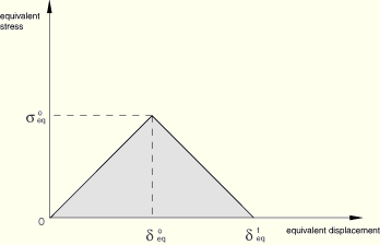
To alleviate mesh dependency during material softening, ABAQUS introduces a characteristic length into the formulation, so that the constitutive law is expressed as a stress-displacement relation. The damage variable will evolve such that the stress-displacement behaves as shown in Figure 19.3.3–1 in each of the four failure modes. The positive slope of the stress-displacement curve prior to damage initiation corresponds to linear elastic material behavior; the negative slope after damage initiation is achieved by evolution of the respective damage variables according to the equations shown below.
Equivalent displacement and stress for each of the four damage modes are defined as follows:
Fiber tension ![]() :
:
![]()
![]()
Fiber compression ![]() :
:
![]()
![]()
Matrix tension ![]() :
:
![]()
![]()
Matrix compression ![]() :
:
![]()
![]()
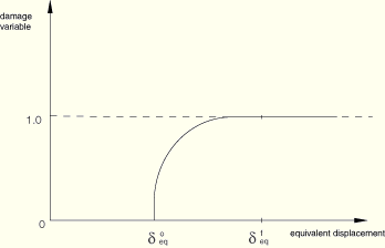
After damage initiation (i.e., ![]() ) for the behavior shown in Figure 19.3.3–1, the damage variable for a particular mode is given by the following expression
) for the behavior shown in Figure 19.3.3–1, the damage variable for a particular mode is given by the following expression
![]()
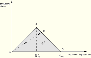
Unloading from a partially damaged state, such as point B in Figure 19.3.3–3, occurs along a linear path toward the origin in the plot of equivalent stress vs. equivalent displacement; this same path is followed back to point B upon reloading as shown in the figure.
| Input File Usage: | Use the following option to define the damage evolution law: |
*DAMAGE EVOLUTION, TYPE=ENERGY, SOFTENING=LINEAR where |
| ABAQUS/CAE Usage: | Property module: material editor: Mechanical |
You have control over how ABAQUS treats elements with severe damage. By default, the upper bound to all damage variables at a material point is![]() . You can reduce this upper bound as discussed in “Controlling element deletion and maximum degradation for materials with damage evolution” in “Section controls,” Section 21.1.4.
. You can reduce this upper bound as discussed in “Controlling element deletion and maximum degradation for materials with damage evolution” in “Section controls,” Section 21.1.4.
By default, an element is removed (deleted) once damage variables for all failure modes at all material points reach ![]() (see “Controlling element deletion and maximum degradation for materials with damage evolution” in “Section controls,” Section 21.1.4). If an element is removed, the output variable STATUS is set to zero for the element, and it offers no resistance to subsequent deformation. However, the element still remains in the ABAQUS model and is visible in the Visualization module of ABAQUS/CAE (ABAQUS/Viewer). You can choose to suppress the display of removed elements by creating a display group consisting of all elements with STATUS equal to 1.0 (see “Selection methods for creating or editing a display group,” Section 52.2.2 of the ABAQUS/CAE User's Manual).
(see “Controlling element deletion and maximum degradation for materials with damage evolution” in “Section controls,” Section 21.1.4). If an element is removed, the output variable STATUS is set to zero for the element, and it offers no resistance to subsequent deformation. However, the element still remains in the ABAQUS model and is visible in the Visualization module of ABAQUS/CAE (ABAQUS/Viewer). You can choose to suppress the display of removed elements by creating a display group consisting of all elements with STATUS equal to 1.0 (see “Selection methods for creating or editing a display group,” Section 52.2.2 of the ABAQUS/CAE User's Manual).
Alternatively, you can specify that an element should remain in the model even after all of the damage variables reach ![]() . In this case, once all the damage variables reach the maximum value, the stiffness,
. In this case, once all the damage variables reach the maximum value, the stiffness, ![]() , remains constant (see the expression for
, remains constant (see the expression for ![]() earlier in this section).
earlier in this section).
When elements are removed from the model, their nodes will still remain in the model even if they are not attached to any active elements. When the solution progresses, these nodes might undergo non-physical displacements due to the extrapolation scheme used in ABAQUS/Standard to speed up the solution (see “Convergence criteria for nonlinear problems,” Section 7.2.3). These non-physical displacements can be prevented by turning off the extrapolation. In addition, applying a point load to a node that is not attached to an active element will cause convergence difficulties since there is no stiffness to resist the load. It is the responsibility of the user to prevent such situations.
Material models exhibiting softening behavior and stiffness degradation often lead to severe convergence difficulties in implicit analysis programs, such as ABAQUS/Standard. You can overcome some of these convergence difficulties by using the viscous regularization scheme, which causes the tangent stiffness matrix of the softening material to be positive for sufficiently small time increments.
In this regularization scheme a viscous damage variable is defined by the evolution equation:
![]()
![]()
The approximate amount of energy associated with viscous regularization over the whole model or over an element set is available using output variable ALLCD.
You can specify different values of viscous coefficients for different failure modes.
| Input File Usage: | Use the following option to define viscous coefficients: |
*DAMAGE STABILIZATION where |
| ABAQUS/CAE Usage: | Property module: material editor: Mechanical |
Alternatively, you can specify the viscous coefficients as part of a section controls definition. In this case the same viscous coefficient will be applied to all failure modes. For more information, see “Using viscous regularization with cohesive elements, connector elements, and elements with plane stress formulations in ABAQUS/Standard” in “Section controls,” Section 21.1.4.
If stiffness proportional damping is specified in combination with the damage evolution law for fiber-reinforced materials, ABAQUS/Standard calculates the damping stresses using the damaged elastic stiffness.
The damage evolution law for fiber-reinforced materials must be used with elements with a plane stress formulation, which include plane stress, shell, continuum shell, and membrane elements.
In addition to the standard output identifiers available in ABAQUS (“ABAQUS/Standard output variable identifiers,” Section 4.2.1), the following variables relate specifically to damage evolution in the fiber-reinforced composite damage model:
STATUS | Status of the element (the status of an element is 1.0 if the element is active, 0.0 if the element is not). The value of this variable is set to 0.0 only if damage has occurred in all the damage modes. |
DAMAGEFT | Fiber tensile damage variable. |
DAMAGEFC | Fiber compressive damage variable. |
DAMAGEMT | Matrix tensile damage variable. |
DAMAGEMC | Matrix compressive damage variable. |
EDMDDEN | Energy dissipated per unit volume in the element by damage. |
ELDMD | Total energy dissipated in the element by damage. |
DMENER | Energy dissipated per unit volume by damage. |
ALLDMD | Energy dissipated in the whole (or partial) model by damage. |
ECDDEN | Energy per unit volume in the element that is associated with viscous regularization. |
ELCD | Total energy in the element that is associated with viscous regularization. |
CENER | Energy per unit volume that is associated with viscous regularization. |
ALLCD | The approximate amount of energy over the whole model or over an element set that is associated with viscous regularization. |