ABAQUS provides the following models to predict progressive damage and failure:
Progressive damage and failure for ductile metals: ABAQUS/Explicit offers a general capability for modeling progressive damage and failure in ductile metals. The functionality can be used in conjunction with the Mises, Johnson-Cook, Hill, and Drucker-Prager plasticity models (“Damage and failure for ductile metals: overview,” Section 19.2.1). The capability supports the specification of one or more damage initiation criteria, including ductile, shear, forming limit diagram (FLD), forming limit stress diagram (FLSD), Müschenborn-Sonne forming limit diagram (MSFLD), and Marciniak-Kuczynski (M-K) criteria. After damage initiation, the material stiffness is degraded progressively according to the specified damage evolution response. The progressive damage models allow for a smooth degradation of the material stiffness, which makes them suitable for both quasi-static and dynamic situations, a great advantage over the dynamic failure models (“Dynamic failure models,” Section 18.2.8).
Progressive damage and failure for fiber-reinforced materials: ABAQUS/Standard offers a capability to model anisotropic damage in fiber-reinforced materials (“Damage and failure for fiber-reinforced composites: overview,” Section 19.3.1). The response of the undamaged material is assumed to be linearly elastic, and the model is intended to predict behavior of fiber-reinforced materials for which damage can be initiated without a large amount of plastic deformation. The Hashin's initiation criteria are used to predict the onset of damage, and the damage evolution law is based on the energy dissipated during the damage process and linear material softening.
In addition, ABAQUS offers a concrete damaged model (“Concrete damaged plasticity,” Section 18.5.3), dynamic failure models (“Dynamic failure models,” Section 18.2.8), and specialized capabilities for modeling damage and failure in cohesive elements (“Defining the constitutive response of cohesive elements using a traction-separation description,” Section 26.5.6) and in connectors (“Connector damage behavior,” Section 25.2.7).
This section provides an overview of the progressive damage and failure capability and a brief description of the concepts of damage initiation and evolution. The discussion in this section is limited to damage models for ductile metals and fiber-reinforced materials.
ABAQUS offers a general framework for material failure modeling that allows the combination of multiple failure mechanisms acting simultaneously on the same material. Material failure refers to the complete loss of load-carrying capacity that results from progressive degradation of the material stiffness. The stiffness degradation process is modeled using damage mechanics.
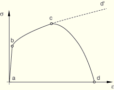
To help understand the failure modeling capabilities in ABAQUS, consider the response of a typical metal specimen during a simple tensile test. The stress-strain response, such as that illustrated in Figure 19.1.1–1, will show distinct phases.
The material response is initially linear elastic,Thus, in ABAQUS the specification of a failure mechanism consists of four distinct parts:
the definition of the effective (or undamaged) material response (e.g., ![]() in Figure 19.1.1–1),
in Figure 19.1.1–1),
a damage initiation criterion (e.g., c in Figure 19.1.1–1),
a damage evolution law (e.g., ![]() in Figure 19.1.1–1), and
in Figure 19.1.1–1), and
a choice of element deletion whereby elements can be removed from the calculations once the material stiffness is fully degraded (e.g., d in Figure 19.1.1–1).
In continuum mechanics the constitutive model is normally expressed in terms of stress-strain relations. When the material exhibits strain-softening behavior, leading to strain localization, this formulation results in a strong mesh dependency of the finite element results in that the energy dissipated decreases upon mesh refinement. In ABAQUS all of the available damage evolution models use a formulation intended to alleviate the mesh dependency. This is accomplished by introducing a characteristic length into the formulation, which in ABAQUS is related to the element size, and expressing the softening part of the constitutive law as a stress-displacement relation. In this case the energy dissipated during the damage process is specified per unit area, not per unit volume. This energy is treated as an additional material parameter, and it is used to compute the displacement at which full material damage occurs. This is consistent with the concept of critical energy release rate as a material parameter for fracture mechanics. This formulation ensures that the correct amount of energy is dissipated and greatly alleviates the mesh dependency.