Product: ABAQUS/Explicit
This example illustrates the use of the results transfer capability in ABAQUS (“Transferring results between ABAQUS/Explicit and ABAQUS/Standard,” Section 9.2.2 of the ABAQUS Analysis User's Manual) to import results from an ABAQUS/Standard steady-state transfer analysis to ABAQUS/Explicit to simulate transient rolling. Examples of loading during transient rolling include impact of a tire with an obstacle or vehicle acceleration. This problem analyzes the impact of a tire with a curb. Because of the small stable time increment necessary for the explicit dynamic procedure and the large time scales involved in simulating quasi-static and steady-state loading, simulating quasi-static inflation loading and steady-state rolling in ABAQUS/Standard provides significant cost savings over performing these simulations in ABAQUS/Explicit. Moreover, the cost to obtain a steady-state rolling simulation in ABAQUS/Explicit increases with rolling speed, whereas in ABAQUS/Standard the cost is independent of the magnitude of the rolling speed.
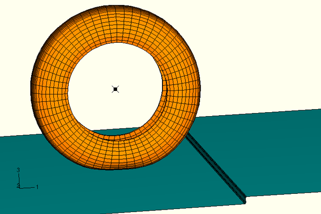
The model used in this example differs slightly from that used in “Symmetric results transfer for a static tire analysis,” Section 3.1.1. Since only elements common to both ABAQUS/Standard and ABAQUS/Explicit can be imported, reduced-integration solid elements are used in this example and nodes in the bead area are attached to rigid elements representing the rim. A plot of the tire before impact with the curb, a 0.025 m high step, is shown in Figure 3.1.6–1. The large rigid body rotation involved in a transient rolling analysis necessitates the use of the nondefault second-order-accurate kinematic formulation in the explicit dynamic analysis. In addition, it is recommended that the enhanced hourglass control scheme be used for both ABAQUS/Standard and ABAQUS/Explicit for all import analyses. Use section controls in the axisymmetric analysis to specify the enhanced hourglass control scheme.
The inflation and footprint preloads are applied in a series of general analysis steps identical to those described in “Symmetric results transfer for a static tire analysis,” Section 3.1.1. Symmetric model generation and symmetric results transfer are used to exploit the symmetric nature of the structure and loading (see “Symmetric model generation,” Section 10.3.1 of the ABAQUS Analysis User's Manual, and “Transferring results from a symmetric mesh or a partial three-dimensional mesh to a full three-dimensional mesh,” Section 10.3.2 of the ABAQUS Analysis User's Manual).
The repeated dynamic impact of tire nodes as they come into contact with the road is an unavoidable source of the high frequency noise that can be seen in the reaction force at the rim. The viscoelastic property of the matrix provides sufficient damping to reduce such high frequency noise. No material damping (mass proportional or stiffness proportional) is necessary in this case. The viscoelastic stress contributions from the steady-state transport analysis are imported into the ABAQUS/Explicit analysis.
An inflation load of 200 kPa is applied to the axisymmetric half-tire model in importrolling_axi_half.inp. This load is followed by a footprint load of 1650 N applied to the three-dimensional half-tire model in importrolling_symmetric.inp, and subsequently results are transferred to the full tire model with the complete footprint load of 3300 N.
The rolling analysis involves rolling the tire up to free rolling conditions. As in “Steady-state rolling analysis of a tire,” Section 3.1.2, a translational velocity of 10 km/h is applied to the tire. The free rolling velocity of the tire is determined in an independent analysis similar to the one described in “Steady-state rolling analysis of a tire,” Section 3.1.2. The rolling velocity corresponding to free rolling conditions is 8.9759 rad/s. Inertia loads are accounted for in this example, since the objective is to import results to a transient dynamic analysis in which inertial effects should be considered during impact with the curb. Viscoelastic effects in the rubber matrix are also included, since viscolasticity is the primary damping mechanism present in the tire.
During the transient dynamic analysis, the tire is moved forward with a prescribed velocity of 10 km/h and the vehicle load is applied to the rim reference node. The tire is allowed to rotate freely about the axle. All other degrees of freedom at the road and rim reference nodes are held fixed.
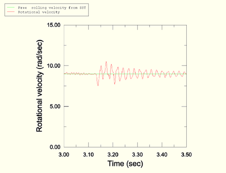
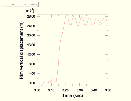
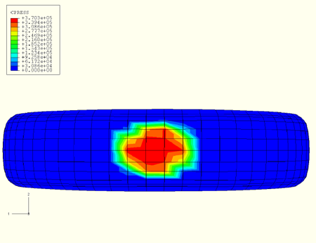
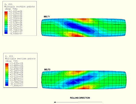
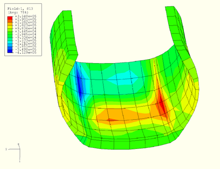
Results are imported and the analysis begins at time t = 3 sec. A plot of the rotational velocity at the rim in Figure 3.1.6–2 shows that the oscillations at the beginning of the analysis are well within acceptable limits. Impact with the curb is initiated after about a quarter rotation of the tire subsequent to import, at approximately t = 3.13 sec. The vertical response of the rim reference node can be seen in Figure 3.1.6–3 and shows oscillations in the tire after impact. The contact patch and the stresses in the belts under steady-state rolling conditions in the transient dynamic solution compare well with the direct steady-state solution from ABAQUS/Standard. The pressure in the footprint can be seen in Figure 3.1.6–4, and the stresses in the belts are plotted in Figure 3.1.6–5. A plot of the shear stress during impact in Figure 3.1.6–6 shows that, as expected, the maximum stress is set up in the shoulder region.
Axisymmetric model, inflation analysis.
Half-symmetric three-dimensional model, inflation and footprint analysis.
Full three-dimensional model, inflation and footprint analysis.
Steady-state, free rolling solution.
Import and transient dynamic analysis.