Product: ABAQUS/Standard
This example illustrates the use of the substructuring capability in ABAQUS (“Defining substructures,” Section 10.1.2 of the ABAQUS Analysis User's Manual) to create a substructure from a tire under inflation and footprint loading. Use of tire substructures is often seen in vehicle dynamic analyses where substantial cost savings are made using substructures instead of the whole tire model. Since tires behave very nonlinearly, it is essential that the change in response due to preloads is built into the substructure. Here the substructure must be generated in a preloaded state. Some special considerations for creating substructures with preloads involving contact are also discussed.
A description of the tire model used is given in “Symmetric results transfer for a static tire analysis,” Section 3.1.1. In this problem inflation and fooptrint preloads are applied in a series of general analysis steps identical to “Symmetric results transfer for a static tire analysis,” Section 3.1.1. The *SYMMETRIC MODEL GENERATION and *SYMMETRIC RESULTS TRANSFER options are used to exploit the symmetric nature of the structure and loading. Nodes in the bead area are tied to the rigid body representing the rim.
The substructure's retained nodes include the rim node and all nodes in the footprint. To enhance the dynamic response of the substructure, these interfacial degrees of freedom are augmented with generalized degrees of freedom associated with the first 20 fixed interface eigenmodes. Depending on the nature of the loading, it may be necessary to increase the number of generalized degrees of freedom to cover a sufficient range of frequencies. The extra cost incurred due to the addition of the extra frequency extraction step is offset by the enhanced dynamic response of the substructure.
An inflation load of 200 kPa is applied in the axisymmetric half-tire model contained in substructtire_axi_half.inp. This is followed by a footprint load of 1650 N applied to the three-dimensional half-tire model given in substructtire_symmetric.inp; and, subsequently, results are transferred to the full tire model with the complete footprint load of 3300 N. All of these steps are run with the NLGEOM=YES parameter, so all preload effects including stress stiffening are taken into account when the substructure is generated.
To retain degrees of freedom that are involved in contact constraints at the footprint, it is necessary to replace the contact constraints with boundary conditions. This is done once the footprint solution is obtained by fixing the retained nodes in the deformed state and using the *MODEL CHANGE option to remove the contact pair between the footprint patch and the road surface. Without this change, the contact constraints produce large stiffness terms in the substructure stiffness that can produce non-physical behavior at the usage level. The mechanical response of the substructure is unchanged since the *BOUNDARY, FIXED option is used to hold the tire in its deformed state. These boundary conditions on the retained degrees of freedom are then released in the *SUBSTRUCTURE GENERATE step, in which they are replaced with concentrated loads. To carry out these steps, it is necessary to obtain the list of nodes in contact with the road. Hence, the substructure is generated in a restart analysis following the analysis with the preloads. This makes it possible to construct the list of nodes that are involved in contact with the road at the end of the preloading. It is necessary to specify the *MODEL CHANGE option with the ACTIVATE parameter in the analysis prior to substructure generation to enable the removal of the contact constraints.
To enhance the dynamic response of the substructure, several restrained eigenmodes are included as generalized degrees of freedom. These restrained eigenmodes are obtained from a *FREQUENCY step with all the retained degrees of freedom restrained. In this example the first 20 eigenmodes, corresponding to a frequency range of 50 to 134 Hz, are computed. With 67 nodes in the footprint, one rim node with six degrees of freedom, and 20 generalized degrees of freedom, the substructure has 227 degrees of freedom.
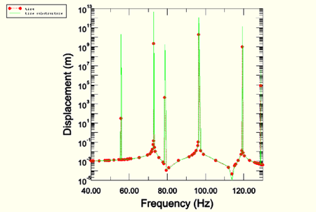
At the usage level the nodes that form the footprint patch in the tire model are restrained to a single node. The steady-state response of the substructure to harmonic footprint loading is analyzed over a range of frequencies from 40 to 130 Hz.
A steady-state dynamic analysis of the substructure with *STEADY STATE DYNAMICS, DIRECT is relatively inexpensive compared to running a similar analysis with the entire tire model. The results for the frequency sweep are shown in Figure 3.1.4–1, which compares the response of the substructure to the response of the entire tire model. All resonances in the tire model are captured by the substructure. This result shows that, although the static response of the tire is used to condense the stiffness and the mass for the retained degrees of freedom, relatively few generalized degrees of freedom can adequately enhance the dynamic response of the substructure. However, the associated expense of calculating the restrained eigenmodes must be taken into account when considering the total cost.
The tire model used for comparison in this example is the same as the model used in “Symmetric results transfer for a static tire analysis,” Section 3.1.1, with one difference. Friction is activated in a step prior to the *STEADY STATE DYNAMICS step to activate constraints in the contact tangential direction on nodes in the footprint so that constraints equivalent to those applied on the footprint nodes in the substructure model are produced.
Axisymmetric model, inflation analysis.
Partial three-dimensional model, footprint analysis.
Full three-dimensional model, final equilibrium analysis.
Substructure generation analysis.
Usage level model with steady-state dynamics analysis.