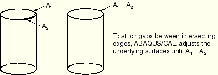
When you select this option, ABAQUS/CAE tries to join adjoining faces along their free edges. The intent of stitching is usually to create a solid part. Stitching edges usually results in valid geometry. ABAQUS/CAE stitches gaps between trimmed surfaces by adjusting the underlying surfaces until the edges intersect. Figure 47–8 illustrates the stitching process.
ABAQUS/CAE tries to recognize the edges of a solid from a set of trimmed surfaces. If the edges of each trimmed surface are close to an edge of an adjacent surface (within the tolerance limitations of ABAQUS/CAE), ABAQUS/CAE stitches the trimmed surfaces. The end result of stitching is a B-rep solid in which the edge definition is shared between the two intersecting surfaces. For more information on B-rep solids, see “How do solid modelers represent a solid?,” Section 10.1.6. Stitching fails in the presence of wires or internal faces.When you import an IGES- or VDA-FS-format part, ABAQUS/CAE stitches the part by default. However, because of the internal tolerances of IGES- and VDA-FS-format parts, the resulting representation of small features may not match the geometry that was intended in the original file.
In some cases stitching an IGES- or VDA-FS-format part results in ABAQUS/CAE importing a single part that should have been imported as separate parts. If you copy the imported part to a new part, you can choose to separate disconnected regions into separate parts. For more information, see “Copying a part,” Section 11.18.3.