ABAQUS/CAE provides tools that allow you to import a sketch, a part, or an assembly into the current model. When you import a sketch or a planar part or assembly, the process is usually straightforward. However, when you import a solid, you may find that you have to perform some additional steps to obtain a satisfactory result. To understand what the steps accomplish and why you need to perform them, you need to understand how solids are represented by solid modelers.
As modeling systems have evolved during the last 30 years, the techniques used to represent a solid body have also evolved. Each new generation of modelers incorporates more knowledge about the construction of the body and relies less on the sheer volume of data points to describe a solid.
Wireframe
The original CAD systems used two-dimensional wireframes to replicate traditional mechanical drawings. Later versions introduced three-dimensionality in the form of isometric views and perspective views. In a wireframe a solid body is represented by a set of curves that define the edges of the body; however, the system has no information about the surfaces between the edges. A wireframe model defines an object by its edges and vertices; as a result the wireframe representation of a solid has limited use. For example, you cannot calculate the volume of the solid, and you cannot mesh the solid.
Trimmed surface
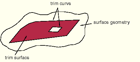
Later systems introduced the concept of trimmed surfaces, as shown in Figure 10–1.
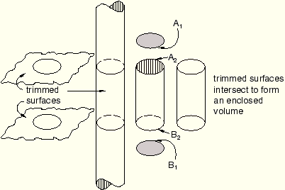
A trimmed surface is defined by a combination of surface geometry and trim curves. The surface geometry is a general expression for the surface; the trim curves form a closed loop on the surface geometry and define the boundary of the surface. A surface can also have multiple internal trim curve surfaces. A solid is defined as a set of trimmed surfaces that form an enclosed volume.For example, a cylinder can be defined from three trimmed surfaces as shown in Figure 10–2.
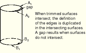
Each surface includes a set of edges that define the boundary of the surface. The flat trimmed surface at the top of the cylinder contains trim curve A1. The flat trimmed surface at the base of the cylinder contains trim curve B1. The cylindrical trimmed surface is bounded by two trim curves—A2 and B2. When two trimmed surfaces intersect, the definition of the resulting edge is duplicated by each surface. There is no information to indicate that a group of trimmed surfaces comprise a solid.The edges of the solid are well defined when the intersecting surfaces are planar, cylindrical, or spherical. However, when more complex curves intersect, the resulting edge must be described by a polynomial expression that approximates the intersection of the two faces. The accuracy of the approximation depends on the order of the polynomial expression. If an edge does not lie on either surface, a gap is created and the solid is considered invalid. Figure 10–3 illustrates a gap between trimmed surfaces.
You can use the Repair toolset to stitch gaps. For more information, see “What is stitching?,” Section 47.3.Both the IGES and VDA-FS standards use trimmed surfaces. Most of the problems that can occur during import arise from the translation of a trimmed surface from the original file into a form recognized by ABAQUS/CAE.
B-rep
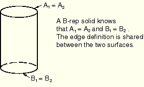
More recently, solid modelers have introduced the concept of a “boundary representation,” or “B-rep,” to define a solid object. A B-rep solid is similar to a solid defined by a set of trimmed surfaces; however, a B-rep solid includes additional information about the faces, edges, and vertices that are generated when the surfaces intersect to form the solid. ABAQUS/CAE uses ACIS to store geometric entities, and ACIS uses the concept of B-reps. Figure 10–4 illustrates the cylinder defined as a B-rep solid.
Unlike a solid represented by only trimmed surfaces, a B-rep solid does not duplicate edges that are shared between two surfaces. In a B-rep solid one trimmed surface defines the shared edge and the second edge refers to that definition. For the B-rep solid to be recreated correctly, it must be possible to duplicate the trim curve defined by the first surface along the geometry of the second surface. In some cases ACIS will stitch adjacent edges to create the B-rep solid.
The IGES and STEP standards include the concept of B-reps, although IGES calls them Manifold Solid B-rep Objects or MSBOs. If you import an IGES or STEP file containing two or more trimmed surfaces that are close enough to be stitched together into a B-rep solid, ABAQUS/CAE groups the surfaces together as a single solid entity. The VDA-FS standard does not include the concept of B-rep solids; VDA-FS uses only trimmed surfaces to define a solid.