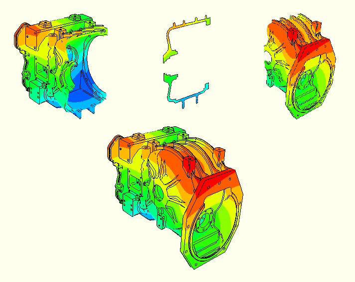
View cuts allow you to cut planar or deformable sections through a model to see the interior of the model. For example, Figure 34–1 shows how a planar view cut can be used to cut through a contour plot of a gearbox model.
Figure 34–1 Planar view cut through a contour plot of a gearbox model. Top, left to right: the model below the cut, on the cut, and above the cut; bottom: the entire model.
a plane,
a cylinder,
a sphere, or
an isosurface corresponding to a constant value of a field variable.
To display the cut section of your model, you activate a cut and choose whether to display the model on the cut, above the cut, and/or below the cut, as illustrated in Figure 34–1. The cut itself is never visible. For planar cuts the portion of the model below the cut is defined as that part located on the negative side of the plane (relative to the orientation of the normal to the plane). For cylindrical and spherical cuts the portion of the model below the cut is defined as that part located at radii less than the radius of the cut shape. For an isosurface cut the portion of the model below the cut is defined as that part located at isovalues less than the specified isovalue. By default, ABAQUS/CAE displays the model on and below the cut.
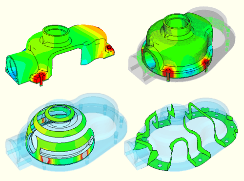
You can select different plot options for the portions of the model below the cut, on the cut, and above the cut; for example, in Figure 34–2 some portions of the model are displayed with translucency activated, while others are displayed with no translucency.
Only one cut can be active (used to display the model in the current viewport) at a time. You can activate view cuts on undeformed, deformed, contour (texture-mapped only), symbol, or material orientation plots. Labels, symbols, and material orientation triads are not projected onto the cut. However, for symbol and material orientation plots, ABAQUS/CAE displays symbols and material orientation triads at all integration points for each element included in the view, even if the element is partially cut.
Plots with an active view cut can be animated; the view cut will be updated for each animation frame. View cuts cannot be activated on tessellated contour plots; swept, shrunk, or extruded plots; or highly refined plots (medium, fine, or extra fine).
By default, ABAQUS/CAE caches the result values used to generate images of a cut model in memory to improve performance. However, you can disable results caching for cut fields to decrease memory usage if necessary; see “Controlling results caching,” Section 24.5.10, for more information.
For plots of the deformed model, you can choose to have the cut follow the deformation; i.e., the cut surface will be calculated relative to a reference frame, and the cut deformation will match the deformation of the model.
You can reposition cuts on your model: planar cuts can be rotated or translated, while the other cut shapes can only be translated.
You can select a cut (either active or inactive) in the View Cut Manager to position, edit, copy, rename, or delete it. Selecting a cut in the manager is not the same as activating the cut. A cut can be both selected and active, unselected and active, or selected and inactive. Figure 34–3 shows an example of the information displayed in the view cut manager.