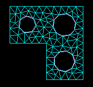
Free meshing with triangular elements can be applied to any planar or curved surface, and the part can be precise or imprecise. For more information, see “What is a valid and precise part?,” Section 10.2.1. A free mesh of triangular elements matches the mesh seeds exactly. This meshing technique can handle large variations in element size, which is useful when you want to refine only part of a mesh. The time taken for ABAQUS/CAE to compute a free triangular mesh grows approximately linearly with the number of elements and nodes. Figure 17–69 shows an example of a mesh generated using this technique.
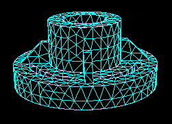
Free meshing with tetrahedral elements can be applied to almost any three-dimensional region; in fact, very complex models can be meshed using this technique without the help of partitioning. Free meshing with tetrahedral elements is similar to free meshing with triangular elements in that the part can be precise or imprecise. In general, ABAQUS/CAE matches the mesh seeds exactly although the mesh may be finer around small holes if the mesh seeds are not fully constrained. Figure 17–70 shows an example of a free tetrahedral mesh.
Free meshing of three-dimensional solids using hexahedral elements is not supported.You should use the Query toolset in the Part module or the Mesh module to check the geometry of the parts or of the assembly before you try to generate a free mesh with tetrahedral elements. You should check the following:
There are no free edges in the solid.
There are no short edges, small faces, or small face corner angles.
When you create a free mesh with tetrahedral elements, you can choose to use the default mesh generation algorithm, or you can choose the algorithm that was included with Version 6.4 of ABAQUS/CAE and earlier. The default algorithm is significantly more robust, particularly when meshing complex shapes and thin solids. In addition, the default algorithm allows you to increase the size of the interior elements. If the mesh density is adequate for the model being analyzed and the areas of interest are on the mesh boundary, increasing the size of the interior elements will increase the computational efficiency.
When you are using free meshing to create triangular elements on a surface, you can allow ABAQUS/CAE to decide whether mapped meshing is appropriate. (Mapped meshing is the same as structured meshing but applies only to four-sided regions.) For more information, see “What is mapped meshing?,” Section 17.8.2, and “When can ABAQUS/CAE apply mapped meshing?,” Section 17.8.6. ABAQUS/CAE replaces free triangular meshing with mapped triangular meshing only when it is likely that the resulting mesh quality will be improved. However, when you allow ABAQUS/CAE to apply mapped meshing where appropriate, the meshing process may be significantly slower. In addition, the minor adjustments that ABAQUS/CAE makes to the mesh seeding may be undesirable.
Similarly, when you are using free meshing to create tetrahedral elements, you can allow ABAQUS/CAE to decide whether mapped meshing is appropriate. After ABAQUS/CAE determines that the resulting mesh quality will be improved, it replaces free meshing with mapped meshing on simple boundary faces and converts the resulting triangles into tetrahedral elements.
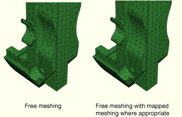
Figure 17–71 shows the effect of allowing mapped meshing where appropriate in a free mesh of a solid part using tetrahedral elements. The mesh quality is improved in four-sided regions that can be mapped meshed.
To view the internal tetrahedral elements generated by ABAQUS/CAE, you can create a new orphan mesh part from the meshed part and use display groups to remove selected elements. You can also view the internal elements after the analysis is complete by using view cuts in the Visualization module. For more information, see Chapter 52, “Using display groups to display subsets of your model,” and Chapter 34, “Cutting through a model.”