Products: ABAQUS/Explicit ABAQUS/CAE
Initial clearances for surface interactions included in the general contact domain:
are set to zero automatically for small initial overclosures (e.g., for small penetrations caused by numerical roundoff when a graphical preprocessor such as ABAQUS/CAE is used);
can be specified to resolve large initial overclosures that are not resolved automatically;
can be specified to separate entangled double-sided surfaces;
can be specified to model an initial gap between surfaces;
are enforced without creating any strains or momentum in the model; and
should not be specified to correct gross errors in the mesh design.
ABAQUS/Explicit will automatically adjust the positions of surfaces to remove small initial overclosures that exist in the general contact domain in the first step of a simulation. The adjustments are made with strain-free initial displacements. This automatic adjustment of surface position is intended to correct only minor mismatches associated with mesh generation.
Conflicting adjustments from separate contacts, boundary conditions, tie constraints, and rigid body constraints can cause incomplete resolution of initial overclosures. This can occur, for example, when a slave node is pinched between two master facets. Initial overclosures that are not resolved by repositioning nodes are stored as temporary contact offsets to avoid large contact forces at the beginning of an analysis. The penalty contact force is computed as ![]() ; where k is the penalty stiffness,
; where k is the penalty stiffness, ![]() is the initial unresolved penetration distance, and
is the initial unresolved penetration distance, and ![]() is the current penetration distance. If
is the current penetration distance. If ![]() ever decreases below
ever decreases below ![]() ,
, ![]() is reset to
is reset to ![]() .
.
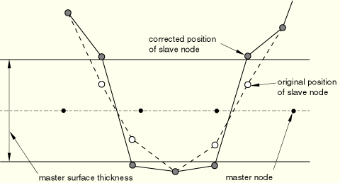
Because of the lack of a unique outward direction from double-sided facets, the resolution of large initial penetrations for double-sided surfaces can be difficult. Initial penetration will be detected only when a slave node lies within the thickness of the underlying element, and the initial penetration will be resolved by moving the slave node to the nearest free surface as shown in Figure 29.3.5–1.
Slave nodes that are trapped on opposite sides of a double-sided master surface will often lead to serious problems, which may not become apparent until later in the analysis. Surfaces that are initially crossed often indicate a modeling problem for single-sided surfaces as well, because the initial search for slave nodes in the interior of solids is limited to a distance of about 15% of the facet dimensions; slave nodes more deeply penetrated than this are ignored by the algorithm to adjust initial overclosures.
Diagnostic testing that identifies regions in which surfaces are crossed in the initial configuration is activated by default. When the diagnostic tests are activated, a warning message is issued to the message (.msg) file if two adjacent slave nodes (connected by a facet edge) are detected on opposite sides of a master surface. No such warning is issued for node-based surface nodes on opposite sides of a master surface, because adjacency cannot be determined among the node-based surface nodes. In some cases involving corners of master surfaces this warning message may be issued even though adjacent slave nodes are really on the same side of a master surface. The CPU cost of performing diagnostic testing on large models is potentially significant. You can choose to deactivate the diagnostic testing and avoid the extra CPU cost in such cases.
| Input File Usage: | Use the following option to deactivate diagnostic testing for initially crossed surfaces: |
*DIAGNOSTICS, DETECT CROSSED SURFACES=OFF |
| ABAQUS/CAE Usage: | Diagnostic testing for initially crossed surfaces is not supported in ABAQUS/CAE. |
If the general contact domain is created in steps other than the first step (i.e., the contact definition follows a step in which no contact was defined) or if an ABAQUS/Standard analysis is imported into ABAQUS/Explicit, initial penetrations are stored as temporary contact offsets that do not generate contact forces. However, deep penetrations may not be treated correctly; they may be ignored or, in the case of penetrations past the midsurface of shells, the wrong contact directions may be used. Initial overclosure and crossed surface diagnostics can be requested to diagnose these problems.
If the general contact domain is extended after the first step, ABAQUS/Explicit does not take any special actions to gradually resolve initial penetrations for the newly introduced interactions: penalty contact forces will be applied proportional to the penetration, or the penetration may be ignored. In addition, initial overclosure and crossed surface diagnostics are not available for these new interactions.
In some cases the default algorithm will not correctly resolve initial overclosures, or a precise initial gap (i.e., a positive clearance) between surfaces may need to be modeled. Specifically, deep penetrations may be ignored, tangled double-sided surfaces may not be separated correctly (see Figure 29.3.5–1), and gaps between curved surfaces in the discretized model may be inconsistent with the non-discretized model. To resolve these issues, you can define contact clearances and assign them to contact interactions. Examples are given below.
You must assign a name to each contact clearance definition that is used to associate the clearance definition with a contact interaction.
| Input File Usage: | *CONTACT CLEARANCE, NAME=clearance_name |
| ABAQUS/CAE Usage: | Contact clearances for general contact are not supported in ABAQUS/CAE. |
Clearances are applied to the model by adjusting the nodal coordinates or by creating contact offsets. By default, contact clearances are resolved by adjusting the nodal coordinates without creating strain or momentum in the model (this method can be used only in the first step of an analysis). Alternatively, contact offsets can be created for clearance specifications. These offsets are permanent (as opposed to temporary offsets created during the default initial overclosure resolution procedure) and are not ramped to zero as the surfaces separate. Contact offsets will also be created for clearances specified via nodal adjustments if the clearance violations cannot be resolved due to conflicting adjustments from separate contacts, boundary conditions, tie constraints, or rigid body constraints. Clearances can be applied via contact offsets in steps in which the whole contact domain is newly defined (i.e., no contact was defined in the previous step) and in the first step of an import analysis.
| Input File Usage: | Use the following option to apply contact clearances by adjusting the nodal coordinates (default): |
*CONTACT CLEARANCE, NAME=clearance_name, ADJUST=YES Use the following option to apply contact clearances by creating contact offsets: *CONTACT CLEARANCE, NAME=clearance_name, ADJUST=NO |
| ABAQUS/CAE Usage: | Contact clearances for general contact are not supported in ABAQUS/CAE. |
You can define the clearance as a single value for the whole interaction or as a nodal distribution to define a clearance per slave node (see “Distribution definition,” Section 2.7.1). If a distribution is defined and the clearance is omitted for a slave node, the clearance value will be interpolated from the values at the master nodes. The slave node will be ignored if clearance values are specified for neither the slave node nor all of the nodes of the nearest master face.
The clearance values must be non-negative for slave nodes on solid element surfaces. The default value is 0.0 if a value or distribution is not given.
| Input File Usage: | *CONTACT CLEARANCE, NAME=clearance_name, CLEARANCE=value or distribution_name |
| ABAQUS/CAE Usage: | Contact clearances for general contact are not supported in ABAQUS/CAE. |
You can specify search distances to define “zones” above and below the surfaces. Slave nodes that lie within these zones will be given the specified clearance values with respect to their closest master faces. Nodes whose closest point is a perimeter edge will be excluded from the clearance specification.
The default value for each search distance for solid elements is approximately one-tenth of the element size of the elements attached to the slave node. The default value for each search distance for structural elements (e.g., shell elements) is the thickness associated with the slave node.
| Input File Usage: | *CONTACT CLEARANCE, NAME=clearance_name, SEARCH ABOVE=value, SEARCH BELOW=value |
| ABAQUS/CAE Usage: | Contact clearances for general contact are not supported in ABAQUS/CAE. |
You can assign initial clearance definitions to node-to-face interactions (except self-contact interactions) in the general contact domain. Initial clearance definitions cannot be assigned to node-to-analytical rigid surface interactions. For node-to face interactions, the clearances defined between two surfaces apply to the interaction between the slave nodes in each surface and the whole of the other surface. When nodal adjustments are used to resolve clearance violations, the adjustments are made to satisfy the clearance specification with respect to each slave node's nearest master face in the initial configuration. Contact offsets are set to the value of the clearance violation between each slave node and its nearest master face in the initial configuration, and the slave nodes are then offset by that value with respect to the whole of the other surface during the analysis.
The surfaces specified must be single-sided and cannot contain complex intersections of faces (i.e., an edge cannot be connected to more than two faces) or discontinuous normals. Surfaces defined on solid elements will satisfy these requirements automatically. These restrictions arise from the definition of a clearance for surfaces on double-sided elements: a node has a positive (negative) clearance with respect to a surface if it is above (below) the surface as defined by the surface normal (see Figure 29.3.5–2). A negative clearance of a node with respect to a surface on double-sided elements does not indicate a state of penetration, but rather that the node has a gap with the other side of the elements underlying the surface.
By default, clearances are applied to all master-slave views of the surface pair that exist in the contact domain. In addition, if clearances between two element-based surfaces are specified to be resolved via nodal adjustments, the nodal adjustment procedure can be directed to perform the adjustments for one master-slave view of the surface pair (this applies only to the nodal adjustment procedure and does not apply to the contact formulation used between the surfaces during the analysis).| Input File Usage: | Use the following option to specify clearances for all master-slave views of the given surface pair (default): |
*CONTACT CLEARANCE ASSIGNMENT
surface_1, surface_2, clearance_name
Use the following option to specify clearances between the nodes of the second surface and the faces of the first surface (the first surface is treated as the master surface): *CONTACT CLEARANCE ASSIGNMENT surface_1, surface_2, clearance_name, MASTER Use the following option to specify clearances between the nodes of the first surface and the faces of the second surface (the first surface is treated as the slave surface): *CONTACT CLEARANCE ASSIGNMENT surface_1, surface_2, clearance_name, SLAVE |
| ABAQUS/CAE Usage: | Contact clearances for general contact are not supported in ABAQUS/CAE. |
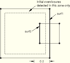
The default algorithm to resolve initial overclosures does not detect penetrations of solid element surfaces that are greater than approximately 15% of the dimension of facets attached to the slave node. Figure 29.3.5–3 shows two solid elements with large initial penetrations that will not be detected during the default initial overclosure resolution procedure.
A zero clearance can be defined explicitly for the overclosed portions of this model to resolve the initial overclosures. Define the clearance definition as follows:
*CONTACT CLEARANCE, NAME=c1, ADJUST=YES, SEARCH BELOW=0.2
SEARCH ABOVE=0.0
and assign it to the interaction between surf1 and surf2:
*CONTACT
*CONTACT CLEARANCE ASSIGNMENT
surf1, surf2, c1
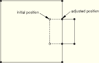
The resulting adjustment is shown in Figure 29.3.5–4.
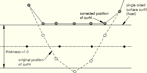
Adjusting the nodal coordinates may degrade the mesh geometry by creating imperfections that were not initially present, may reduce the element size and correspondingly the stable time increment size, or may cause elements to invert and prevent the analysis from continuing. In such cases it is preferable to bypass the nodal coordinate adjustments and specify the storage of a contact offset.The initial overclosure adjustment algorithm must also be directed to separate entangled double-sided surfaces. Figure 29.3.5–1 shows the default adjustments made for entangled shell surfaces assuming the nodes of surf3 have fixed boundary conditions. Figure 29.3.5–5 shows the adjustments made from the following clearance definition and assignment:
*CONTACT CLEARANCE, NAME=c2, ADJUST=YES, SEARCH BELOW=1.5, SEARCH ABOVE=0.0 ... *CONTACT *CONTACT CLEARANCE ASSIGNMENT surf3, surf4, c2If the nodes of surf3 are not fixed, the clearance interaction can be set to pure master-slave (with surf3 defined as the master) to prevent the geometry of surf3 from being modified.
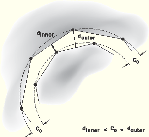
In cases where the geometry of the mesh is important or if nodal adjustments conflict, contact offsets should be created. Conflicting nodal adjustments are a common problem when specifying clearances via nodal adjustment for curved surfaces with a balanced master-slave interaction. Adjustments of nodes tend to change the curvature of curved surfaces because the clearance “constraint” can be satisfied only if the surface meshes are coincident (and a zero clearance is specified) or if the surfaces are flat (see Figure 29.3.5–6).
There are three sources of information on the adjustments of overclosed surfaces: the status (.sta) file, the message (.msg) file, and the output database (.odb) file.
By default, ABAQUS/Explicit writes the nodal adjustments and contact offsets for all nodes in the contact domain to the message (.msg) file along with a summary listing of the maximum initial overclosure for the contact domain to the status (.sta) file. You can choose to suppress the information written to the message file and only write the summary information to the status file.
| Input File Usage: | Use the following option to obtain both detailed diagnostic output to the message file and summary diagnostic output to the status file: |
*DIAGNOSTICS, CONTACT INITIAL OVERCLOSURE=DETAIL (default) Use the following option to obtain only summary diagnostic output to the status file (no contact diagnostics will be written to the message file): *DIAGNOSTICS, CONTACT INITIAL OVERCLOSURE=SUMMARY |
| ABAQUS/CAE Usage: | Detailed diagnostic output requests for contact initial overclosures are not supported in ABAQUS/CAE. |
In the first step the adjustments of surfaces can be viewed in ABAQUS/CAE. Displaced shape plots that show the adjustments to the contact domain in the first step can be plotted for the original field output frame at zero time. Such plots can be viewed in ABAQUS/CAE after a data check analysis (see “Execution procedure for ABAQUS/Standard and ABAQUS/Explicit,” Section 3.2.2).