Products: ABAQUS/Explicit ABAQUS/CAE
ABAQUS/Explicit provides two algorithms for modeling contact and interaction problems: the general contact algorithm and the contact pair algorithm. See “Contact interaction analysis: overview,” Section 29.1.1, for a comparison of the two algorithms. This section describes how to include general contact in an ABAQUS/Explicit analysis, how to specify the regions of the model that may be involved in general contact interactions, and how to obtain output from a general contact analysis.
The general contact algorithm in ABAQUS/Explicit:
is specified as part of the model or history definition of the model;
allows very simple definitions of contact with very few restrictions on the types of surfaces involved;
uses sophisticated tracking algorithms to ensure that proper contact conditions are enforced efficiently;
can be used simultaneously with the contact pair algorithm (i.e., some interactions can be modeled with the general contact algorithm, while others are modeled with the contact pair algorithm);
can be used only with three-dimensional surfaces;
can be used only in mechanical finite-sliding contact analyses; and
does not support kinematic constraint enforcement (contact constraints are enforced with the penalty method).
The definition of a general contact interaction consists of specifying:
the general contact algorithm and defining the contact domain (i.e., the surfaces that interact with one another), as described in this section;
the contact surface properties (“Surface properties for general contact,” Section 29.3.2);
the mechanical contact property models (“Contact properties for general contact,” Section 29.3.3);
the contact formulation (“Contact formulation for general contact,” Section 29.3.4);
the initial clearance between contact surfaces (“Resolving initial overclosures and specifying initial clearances for general contact,” Section 29.3.5); and
the algorithmic contact controls (“Contact controls for general contact,” Section 29.3.6).
The general contact algorithm allows for very general characteristics in the surfaces that it uses, as discussed in “Contact interaction analysis: overview,” Section 29.1.1. For detailed information on defining surfaces in ABAQUS/Explicit for use with the general contact algorithm, see “Defining element-based surfaces,” Section 2.3.2; “Defining node-based surfaces,” Section 2.3.3; “Defining analytical rigid surfaces,” Section 2.3.4; and “Operating on surfaces,” Section 2.3.5.
A convenient method of specifying the contact domain is using cropped surfaces. Such surfaces can be used to perform “contact in a box” by using a contact domain that is enclosed in a specified rectangular box in the original configuration. For more information, see “Operating on surfaces,” Section 2.3.5.
In addition, ABAQUS/Explicit automatically defines an all-inclusive surface that is convenient for prescribing the contact domain, as discussed later in this section. The all-inclusive automatically defined surface includes all element-based surface facets as well as all analytical rigid surfaces.
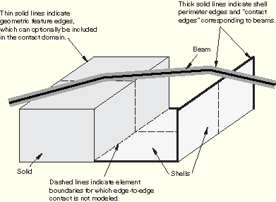
The general contact algorithm generates contact forces to resist node-into-face, node-into-analytical rigid surface, and edge-into-edge contact penetrations. The primary mechanism for enforcing contact is node-to-face contact (the only mechanism used in the contact pair algorithm). If analytical rigid surfaces are present in the contact domain, the general contact algorithm also enforces node-to-analytical rigid surface contact. The general contact algorithm also considers edge-to-edge contact, which is very effective in enforcing contact that cannot be detected as penetrations of nodes into faces. For example, contact between beam segments and shell perimeter edges (see Figure 29.3.1–1) usually is detected only as edge-to-edge contact. The terminology “contact edges” refers to feature edges of surface facets (on both shells and solids) as well as to segments representing beam and truss elements. The contact edges representing beam and truss elements have a circular cross-section, regardless of the actual cross-section of the beam or truss element. The area of the circular cross-section of a beam or truss segment at a node is equal to the minimum cross-sectional area of the adjacent beam or truss elements. The radius of the cross-section is interpolated linearly over the length of the contact edge. Generally, the radius of the contact edge and the radius of the cross-section for a circular beam or truss element are not equivalent. When the axial dimension of a beam or truss element is large compared to the element section radius, the contact radius is close to the section radius over the length of the contact edge. Shell element edges reflect the shell thickness in the normal direction and do not extend past the perimeter (similar to shell nodes and facets). Some numerical rounding of features occurs for both node-to-facet and edge-to-edge contact.
By default, when a surface is used in a general contact interaction, all applicable facets, analytical rigid surfaces, nodes, perimeter edges, and beam and truss segments are included in the contact definition. You can control which feature edges are considered for edge-to-edge contact, as discussed in “Surface properties for general contact,” Section 29.3.2. Geometric feature edges and perimeter edges do not have to be included explicitly in a surface definition (by using edge identifiers) for them to be considered for edge-to-edge contact.
In edge-to-edge contact the surface around each edge is approximated as a cylinder. To model contact between edges that are not cylindrical in shape, surface elements can be attached to the edge nodes using surface-based tie constraints and node-to-face contact can be defined between the surface elements (see “Surface elements,” Section 26.7.1). This technique is useful for modeling geometric details important to the contact definition that are not modeled with the underlying element geometry. Surface elements can also be defined around shell elements in which ABAQUS has reduced the contact thickness (i.e., if the thickness exceeds the surface facet edge lengths or diagonal lengths) so that the true surface thickness can be modeled. However, using surface elements with general contact requires a physically reasonable mass to be associated with the surface element nodes, and care must be taken not to alter the bulk mass properties when transferring mass to the surface elements from the underlying elements.
Two-dimensional surfaces cannot be used with the general contact algorithm.
Only one general contact definition can be active in a step. If a general contact definition does not appear in a step, any general contact definition active in the previous step will be propagated to the current step.
For convenience, general contact can be defined as model data. A general contact definition specified as model data is considered to be defined in the initial step, or “Step 0,” of the analysis; it can be modified or removed in Step 1 or later steps.
| Input File Usage: | Use the following option to indicate the beginning of a general contact definition: |
*CONTACT This option can appear only once per step. |
| ABAQUS/CAE Usage: | Interaction module: Create Interaction: General contact (Explicit) |
You can remove the previously specified general contact definition and specify a new one.
| Input File Usage: | *CONTACT, OP=NEW |
| ABAQUS/CAE Usage: | Interaction module: interaction manager: select interaction, Deactivate |
Alternatively, you can make changes to an existing general contact definition. In this case the existing general contact definition remains active and any additional information specified is appended to the general contact definition.
Contact state information (such as the proper contact normal orientation for double-sided surfaces) is transferred across step boundaries even if the contact domain is modified.
| Input File Usage: | *CONTACT, OP=MOD |
| ABAQUS/CAE Usage: | Interaction module: interaction manager: select interaction, Edit |
Each part of a general contact definition is considered independently when it is modified. For example, the following contact definition is specified in Step 1 (the individual options are discussed later in this section):
*CONTACT
*CONTACT INCLUSIONS
surf_1,
*CONTACT EXCLUSIONS
surf_a, surf_b
This contact definition is then modified in Step 2 with the following input:
*CONTACT, OP=MOD
*CONTACT INCLUSIONS
surf_2, surf_3
*CONTACT EXCLUSIONS
surf_a, surf_c
An equivalent contact definition for Step 2 could be specified as follows:
*CONTACT, OP=NEW
*CONTACT INCLUSIONS
surf_1,
surf_2, surf_3
*CONTACT EXCLUSIONS
surf_a, surf_b
surf_a, surf_c
You specify the regions of the model that can potentially come into contact with each other by defining general contact inclusions and exclusions. Only one contact inclusions definition and one contact exclusions definition are allowed per step.
All contact inclusions in an analysis are applied first, then all contact exclusions are applied, regardless of the order in which they are specified. The contact exclusions take precedence over the contact inclusions. The general contact algorithm will consider only those interactions specified by the contact inclusions definition and not specified by the contact exclusions definition.
General contact interactions typically are defined by specifying self-contact for the default automatically generated surface provided by ABAQUS/Explicit. All surfaces used in the general contact algorithm can span multiple unattached bodies, so self-contact in this algorithm is not limited to contact of a single body with itself. For example, self-contact of a surface that spans two bodies implies contact between the bodies as well as contact of each body with itself.
Define contact inclusions to specify the regions of the model that should be considered for contact purposes.
You can specify self-contact for a default unnamed, all-inclusive surface defined automatically by ABAQUS/Explicit. This default surface contains, with the exceptions noted below, all exterior element faces, all analytical rigid surfaces and all edges based on beam and truss elements in the model, as well as the nodes attached to these faces and edges; in addition, feature edges are included according to the user-specified criteria (see “Surface properties for general contact,” Section 29.3.2). This is the simplest way to define the contact domain. With this approach contact is modeled for all node-to-facet, node-to-analytical rigid surface, and edge-to-edge interactions of the nodes, facets, analytical rigid surfaces, and contact edges of the default surface. This default surface does not include the following:
Nodes that cannot be part of an element-based surface; for example, nodes attached only to point masses or connectors.
Faces, edges, and nodes that belong only to cohesive elements. In fact, this default surface is generated as if cohesive elements were not present. See “Modeling with cohesive elements,” Section 26.5.3, for further discussion of contact modeling issues related to cohesive elements.
| Input File Usage: | Use both of the following options to specify “automatic” contact for the entire model: |
*CONTACT
*CONTACT INCLUSIONS, ALL EXTERIOR
The *CONTACT INCLUSIONS option should have no data lines when the ALL EXTERIOR parameter is used; any data lines specified will be ignored. |
| ABAQUS/CAE Usage: | Interaction module: Create Interaction: General contact (Explicit): Included surface pairs: All* with self |
Alternatively, you can define the general contact domain directly by specifying the individual contact surface pairings. Self-contact will be modeled only if the two surfaces specified in a pair overlap (or are identical) and will be modeled only in the overlapping region.
Multiple surface pairings can be included in the contact domain. At least one surface in each pair must be either an element-based surface or an analytical rigid surface.
| Input File Usage: | Use both of the following options to specify individual contact interactions: |
*CONTACT
*CONTACT INCLUSIONS
surface_1, surface_2
At least one data line must be specified when the ALL EXTERIOR parameter is omitted. Either or both of the data line entries can be left blank, but each data line must contain at least a comma; an error message will be issued for empty data lines. If the first surface name is omitted, the default unnamed, all-inclusive, automatically generated surface is assumed. If the second surface name is omitted or is the same as the first surface name, contact between the first surface and itself is assumed. Leaving both data line entries blank is equivalent to using the ALL EXTERIOR parameter. |
| ABAQUS/CAE Usage: | Interaction module: Create Interaction: General contact (Explicit): Included surface pairs: Selected surface pairs: Edit, select the surfaces in the columns on the left, and click the arrows in the middle to transfer them to the list of included pairs |
The following input specifies that contact should be enforced between the default all-inclusive, automatically generated surface and surface_2, including self-contact in any overlap regions:
*CONTACT
*CONTACT INCLUSIONS
 , surface_2
Either of the following methods can be used to define self-contact for surface_1:
*CONTACT
*CONTACT INCLUSIONS
surface_1,
or
*CONTACT
*CONTACT INCLUSIONS
surface_1, surface_1
The following input can be used to introduce a node-based surface containing point masses to the contact domain as well as specify self-contact for the default all-inclusive, automatically generated surface:
*CONTACT
*CONTACT INCLUSIONS
 ,
 , node_based_surf
You can refine the contact domain definition by specifying the regions of the model to exclude from contact.
The primary motivation for specifying contact exclusions is to avoid physically unreasonable contact interactions. For example, a finite element model may contain multiple forming tools, but not all of the tools participate in the forming process simultaneously; you can specify contact exclusions to prevent certain tools from participating in the contact model in certain steps.
You do not need to be concerned with specifying contact exclusions for parts of the model that are not likely to interact, since these exclusions typically will have minimal effect on computational performance.
Contact will be ignored for all the surface pairings specified, even if these interactions are specified directly or indirectly in the contact inclusions definition.
Multiple surface pairings can be excluded from the contact domain. At least one surface in each pair must be either an element-based surface or an analytical rigid surface. Keep in mind that surfaces can be defined to span multiple unattached bodies, so self-contact exclusions are not limited to exclusions of single-body contact.
| Input File Usage: | Use both of the following options to specify contact exclusions: |
*CONTACT
*CONTACT EXCLUSIONS
surface_1, surface_2
Either or both of the data line entries can be left blank. If the first surface name is omitted, the default unnamed, all-inclusive, automatically generated surface is assumed. If the second surface name is omitted or is the same as the first surface name, contact between the first surface and itself is excluded from the contact domain. |
| ABAQUS/CAE Usage: | Interaction module: Create Interaction: General contact (Explicit): Excluded surface pairs: Edit, select the surfaces in the columns on the left, and click the arrows in the middle to transfer them to the list of excluded pairs |
ABAQUS/Explicit automatically generates contact exclusions for general contact in some situations.
Contact exclusions are generated automatically for interactions that are defined with the contact pair algorithm or surface-based tie constraints to avoid redundant (and possibly inconsistent) enforcement of these interaction constraints. For example, if a contact pair is defined for surface_1 and surface_2 and “automatic” general contact is defined for the entire model, ABAQUS/Explicit would generate a contact exclusion for general contact between surface_1 and surface_2, so that interactions between these surfaces would be modeled only with the contact pair algorithm. These automatically generated contact exclusions are in effect only during the steps in which the contact pair algorithm or surface-based tie constraint interactions are active.
ABAQUS/Explicit automatically generates contact exclusions for self-contact of each rigid body in the model, because it is not possible for a rigid body to contact itself.
When you specify pure master-slave contact surface weighting for a particular general contact surface pair, contact exclusions are generated automatically for the master-slave orientation opposite to that specified (see “Contact formulation for general contact,” Section 29.3.4, for more information on this type of contact exclusion).
The general contact algorithm, unlike the contact pair algorithm, activates and deactivates contact faces and contact edges in the contact domain based on the failure status of the underlying elements. See “Modeling surface erosion” below for details.
The following input specifies that the contact domain is based on self-contact of an all-inclusive, automatically generated surface but that contact (including self-contact in any overlap regions) should be ignored between the all-inclusive, automatically generated surface and surface_2:
*CONTACT
*CONTACT INCLUSIONS, ALL EXTERIOR
*CONTACT EXCLUSIONS
 , surface_2
Either of the following methods can be used to exclude self-contact for surface_1 from the contact domain:
*CONTACT EXCLUSIONS
surface_1,
or
*CONTACT EXCLUSIONS
surface_1, surface_1
General contact allows the use of element-based surfaces to model surface erosion for analyses. If an appropriate “interior” surface is defined, the surface topology will evolve to match the exterior of elements that have not failed. Alternatively, if only one of the bodies can erode, a node-based surface can be used to model surface erosion; this approach can be used with either the general contact or contact pair algorithms. However, even if only one body can erode, it is recommended to define an element-based surface for the eroding body to avoid the usual limitations of node-based surfaces (see “Defining node-based surfaces,” Section 2.3.3).
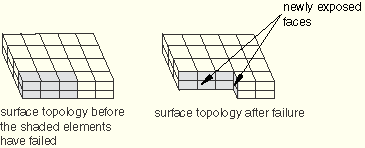
The general contact algorithm modifies the list of contact faces and contact edges that are active in the contact domain based on the failure status of the underlying elements (element failure is discussed in “Dynamic failure models,” Section 18.2.8). General contact considers a face only if its underlying element has not failed and it is not coincident with a face from an adjacent element that has not failed; thus, exterior faces are initially active, and interior faces are initially inactive. Once an element fails, its faces are removed from the contact domain, and any interior faces that have been exposed are activated. A contact edge is removed when all the elements that contain the edge have failed. New contact edges are not created as elements erode. Based on this algorithm, the active contact domain evolves during the analysis as elements fail (see Figure 29.3.1–2 for an example of an eroding solid).
You can control whether contact nodes remain in the contact domain after all the surrounding elements have failed. By default, these nodes remain in the contact domain and act as free-floating point masses that can experience contact with faces that are still part of the contact domain. You can specify that nodes of element-based surfaces should erode (i.e., be removed from the contact domain) once all contact faces and contact edges to which they are attached have eroded. Further discussion of this technique, including reasons for and against nodal erosion, can be found in “Contact controls for general contact,” Section 29.3.6.
For a solid element mesh consisting of elements that may fail, every face that can potentially be involved in contact (both exterior and interior faces) should be included in the contact domain. The general contact algorithm will activate and deactivate faces as necessary when elements fail.
For example, you define an element set ELERODE that contains all the solid elements in the model that refer to a material failure model. First, you must create a surface SURFERODE containing all of the interior and exterior faces of these elements. You could define this surface using the automatic free surface and interior surface generation methods in ABAQUS/Explicit. Assuming all the elements in ELERODE are of type C3D8R, you could alternatively define the surface by specifying the faces S1 through S6 directly. See “Creating surfaces on solid, continuum shell, and cohesive elements” in “Defining element-based surfaces,” Section 2.3.2, for a discussion of these three methods.
Next, you must construct the contact domain. Defining “automatic” general contact for the entire model is not sufficient because the contact domain created when this method is used does not include any interior faces. Therefore, you must define the pairwise interactions with the erodable surface explicitly in the contact inclusions definition, as outlined in Table 29.3.1–1.
Table 29.3.1–1 Contact inclusions definitions.
| Contact inclusions | Input file syntax | ABAQUS/CAE syntax |
|---|---|---|
| Self-contact for the default all-inclusive surface specifies contact between every exterior face in the model | , | First Surface: (All*) Second Surface: (Self) |
| Contact between the default all-inclusive surface and SURFERODE specifies contact between every exterior face and SURFERODE | , SURFERODE | First Surface: (All*) Second Surface: SURFERODE |
| Self-contact for SURFERODE specifies self-contact between the eroding bodies | SURFERODE, | First Surface: SURFERODE Second Surface: (Self) |
Alternatively, you could create a more concise definition of the same contact domain by first defining a surface named SURFALL that includes all exterior faces in the entire model and all interior faces of element set ELERODE. In this case, since all faces (exterior and interior) in the contact domain are defined in one surface, there is no need to define contact explicitly between the exterior and interior faces. It would be adequate to specify only self-contact for SURFALL.
For structural elements, the general contact algorithm checks the underlying elements of the faces (or “contact edges” on beam and truss elements) for failure. Once the underlying element fails, the face is removed. As with solids, feature edges on structural elements are removed once all of the surrounding faces have failed. A perimeter edge (e.g., on the perimeter of a shell element mesh) is removed once the face it is connected to fails. New perimeter edges are not created to conform to the new perimeter created by the removal of a face.
The amount of contact data used to describe the surface topology is proportional to the number of faces included in the contact domain. Including a large number of interior faces in the contact domain can potentially increase memory use significantly compared to analyses in which the contact domain is defined using only exterior faces. Consider creating a surface on a cubic mesh of C3D8R elements with n elements per side. A surface including the exterior faces of the mesh (suitable for modeling contact without element failure) would contain 6n2 element faces. A surface including both exterior and interior faces of the mesh (suitable for modeling contact with element failure for every element in the mesh) would contain 6n3 element faces. For large meshes the memory use can increase easily by an order of magnitude when interior element faces are included in the contact domain to model erosion. Therefore, it is recommended to include only those interior element faces in the contact domain that could possibly participate in contact.
The surfaces that compose the general contact domain are available as output in addition to the contact analysis output variables.
ABAQUS/Explicit generates the following internal surfaces when a general contact domain is defined: General_Contact_Faces_k, General_Contact_Edges_k, and General_Contact_Nodes_k, where k is the step number. General_Contact_Nodes_k contains only nodes in the general contact domain that are not included in the other two surfaces. For example, General_Contact_Faces_2 would contain all surface faces (interior and exterior) that were initially included in the general contact domain for Step 2. These surfaces contain the contact faces, edges, and nodes that were included in the contact domain at the beginning of the step and are not modified to reflect surface erosion. These internal surfaces can be viewed using display groups in the Visualization module of ABAQUS/CAE (see the ABAQUS/CAE User's Manual). The internal surface names used by ABAQUS/Explicit should not appear in the input file.
You can write the contact surface variables associated with general contact interactions to the ABAQUS output database (.odb) file (see “Surface output” in “Output to the output database,” Section 4.1.3, for more information). The available variables are contact pressure, normal contact force, frictional force, and whole surface resultant quantities (i.e., force, moment, center of pressure, and total area in contact).
The generic variables CSTRESS and CFORCE are valid field output requests for general contact in ABAQUS/Explicit. If CSTRESS is requested for the general contact domain, the variable CPRESS (contact pressure) can be contoured in ABAQUS/CAE. If CFORCE is requested for the general contact domain, the variables CNORMF (normal contact force) and CSHEARF (shear contact force) can be plotted as vectors in a symbol plot in ABAQUS/CAE.
For general contact CPRESS is calculated as the magnitude of the net contact normal force (the CNORMF vector) per unit area (it is an unsigned value). This convention for reporting contact pressure is different from the convention used for contact pairs. The direction of action of the net contact pressure for general contact can be determined by examining a plot of CNORMF.
CNORMF and CSHEARF are resultant force quantities. If a double-sided surface is contacted on both sides, the resultant force is a vector sum of the force from each side of the surface (for example, the contact normal force will be zero for a double-sided surface that is pinched with equal and opposite forces on each side of the surface).
Several whole surface contact force-derived variables are available as history output. You can specify the surface from which the contact force resultants will be calculated.
Force distributions on the surface due to general contact are used to calculate the surface force resultants; forces due to contact pair interactions are not included and must be output separately. The contact state of a surface is output as a set of force (CFN, CFS, and CFT) and moment (CMN, CMS, and CMT) resultants with respect to the origin. Additional variables give the total area in contact at a given time (CAREA, defined as the sum of all the facets where there is contact force) and the center of pressure (XN, XS, and XT) on the surface (defined as the point closest to the centroid of the surface that lies on the line of action of the resultant force for which the resultant moment is zero). The last letter of each variable name (except the variable CAREA) denotes which contact force distribution on the surface is used to calculate the resultant: the letter N denotes that the normal contact forces are used to derive the resultant quantity; the letter S denotes that the shear contact forces are used to derive the resultant quantity; and the letter T denotes that the sum of the normal and shear contact forces are used to derive the resultant quantity.
| Input File Usage: | Use the following option to specify the surface from which the contact force resultants will be calculated: |
*CONTACT OUTPUT, SURFACE=surface_name |
| ABAQUS/CAE Usage: | Step module: history output request editor: Domain: General contact surface: surface_name |
When modeling the erosion of surfaces, it is useful to request additional element field output of the element status (output variable STATUS). Failed elements (with an element status of zero) can then be excluded from the display group in the Visualization module of ABAQUS/CAE so that the active contact surface can be identified and contact results on the active contact surface can be viewed.