Products: ABAQUS/Explicit ABAQUS/CAE
Surface property assignments:
can be used to change the contact thickness used for regions of a surface based on structural elements or to add a contact thickness for regions of a surface based on solid elements;
can be used to specify surface offsets for regions of a surface based on shell, membrane, rigid, and surface elements;
can be used to specify which edges of a model should be included in the general contact domain;
can be applied selectively to particular regions within a general contact domain; and
cannot be applied to analytical rigid surfaces.
You can assign nondefault surface properties to surfaces involved in general contact interactions. These properties are considered only when the surfaces are involved in general contact interactions; they are not considered when the surfaces are involved in other interactions such as contact pairs. The general contact algorithm does not consider surface properties specified as part of the surface definition.
Surface property assignments propagate through all analysis steps in which the general contact interaction is active.
The surface names used to specify the regions with nondefault surface properties do not have to correspond to the surface names used to specify the general contact domain. In many cases the contact interaction will be defined for a large domain, while nondefault surface properties will be assigned to a subset of this domain. Any surface property assignments for regions that fall outside the general contact domain will be ignored. The last assignment will take precedence if the specified regions overlap.
| Input File Usage: | *SURFACE PROPERTY ASSIGNMENT, PROPERTY |
This option must be used in conjunction with the *CONTACT option. It should appear at most once per step for each value of the PROPERTY parameter discussed below; the data line can be repeated as often as necessary to assign surface properties to different regions. |
| ABAQUS/CAE Usage: | Interaction module: Create Interaction: General contact (Explicit): Surface Properties |
The default calculation of the nodal surface thickness (described in detail below) is appropriate for most analyses; one exception is sheet forming analysis, in which the thinning of a sheet significantly influences contact. This case can be modeled by specifying that the decreasing parent element thickness should be used. As a third alternative, you can specify a value for the surface thickness. A nonzero thickness can be assigned to solid element surfaces, for example, to model the effect of a finite-thickness surface coating. “Defining element-based surfaces,” Section 2.3.2, contains information on the spatial variation of the surface thickness.
Specifying the original or decreasing thickness results in a zero thickness for node-based surfaces; you can specify a nonzero thickness for a node-based surface used with the general contact algorithm (the contact pair algorithm will not consider a nonzero thickness for such surfaces).
The contact thickness cannot exceed the surface facet edge lengths or diagonal lengths. The general contact algorithm will scale back the contact thickness automatically where necessary without affecting the thickness used in the element computations for the underlying elements. Diagnostic information is provided in the status (.sta) file if such scaling is performed. To bypass this limitation on thickness, the contact surface can be modeled with surface elements (see “Surface elements,” Section 26.7.1). The surface elements must be attached to the underlying elements using a surface-based tie constraint (see “Mesh tie constraints,” Section 28.3.1), and a physically reasonable mass must be associated with the surface elements. This requires a significant fraction of the mass to be transferred to the surface elements from the underlying elements without appreciably altering the bulk mass properties.
The “bull-nose” effect that occurs at shell perimeters with the contact pair algorithm (see “Surface properties for ABAQUS/Explicit contact pairs,” Section 29.4.2) is avoided with the general contact algorithm. Shell element edges, nodes, and facets reflect the shell thickness in the normal direction only and do not extend past the perimeter.
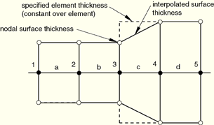
By default, the nodal thickness for surfaces based on shell, membrane, or rigid elements equals the minimum original thickness of the surrounding elements (see Figure 29.3.2–1 and Table 29.3.2–1). The surface thickness within a facet is interpolated from the nodal values; the interpolated surface thickness never extends past the specified element or nodal thickness, which may be significant with respect to initial overclosures. The default nodal surface thickness is zero for regions of a surface based on solid elements.
Table 29.3.2–1 Thicknesses corresponding to Figure 29.3.2–1.
| Node | Element | Specified element thickness | Nodal surface thickness (minimum of adjacent element thicknesses) |
|---|---|---|---|
| 1 | 0.5 | ||
| a | 0.5 | ||
| 2 | 0.5 | ||
| b | 0.5 | ||
| 3 | 0.5 | ||
| c | 0.9 | ||
| 4 | 0.9 | ||
| d | 0.9 | ||
| 5 | 0.9 |
Figure 29.3.2–2 Small discrepancy between the nodal surface thickness and the specified nodal thickness.
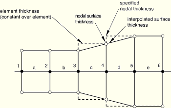
Table 29.3.2–2 Thicknesses corresponding to Figure 29.3.2–2.
| Node | Element | Specified nodal thickness | Element thickness (average of specified nodal thickness) | Nodal surface thickness (minimum of adjacent element thicknesses) |
|---|---|---|---|---|
| 1 | 0.5 | 0.5 | ||
| a | 0.5 | |||
| 2 | 0.5 | 0.5 | ||
| b | 0.5 | |||
| 3 | 0.5 | 0.5 | ||
| c | 0.7 | |||
| 4 | 0.9 | 0.7 | ||
| d | 0.9 | |||
| 5 | 0.9 | 0.9 | ||
| e | 0.9 | |||
| 6 | 0.9 | 0.9 |
| Input File Usage: | Use the following option to use the original thickness of the parent element for the surface thickness (the default): |
*SURFACE PROPERTY ASSIGNMENT, PROPERTY=THICKNESS
surface, ORIGINAL
If the surface name is omitted, a default surface that encompasses the entire general contact domain is assumed. |
| ABAQUS/CAE Usage: | Interaction module: Create Interaction: General contact (Explicit): Surface Properties: Shell/Membrane thickness assignments: Edit: Select surface, click the arrows to transfer surface to list of thickness assignments, and enter ORIGINAL in the Thickness column. |
If you specify that the decreasing parent element thickness should be used, only decreases in the parent element thickness are reflected in the contact surface thickness; if the parent element thickness actually increases during the analysis, the contact thickness will remain constant.
| Input File Usage: | Use the following option to use the decreasing thickness of the parent element for the surface thickness: |
*SURFACE PROPERTY ASSIGNMENT, PROPERTY=THICKNESS
surface, THINNING
If the surface name is omitted, a default surface that encompasses the entire general contact domain is assumed. |
| ABAQUS/CAE Usage: | Interaction module: Create Interaction: General contact (Explicit): Surface Properties: Shell/Membrane thickness assignments: Edit: Select surface, click the arrows to transfer surface to list of thickness assignments, and enter THINNING in the Thickness column. |
You can directly specify the surface thickness value.
| Input File Usage: | Use the following option to specify a value for the surface thickness: |
*SURFACE PROPERTY ASSIGNMENT, PROPERTY=THICKNESS
surface, value
If the surface name is omitted, a default surface that encompasses the entire general contact domain is assumed. |
| ABAQUS/CAE Usage: | Interaction module: Create Interaction: General contact (Explicit): Surface Properties: Shell/Membrane thickness assignments: Edit: Select surface, click the arrows to transfer surface to list of thickness assignments, and enter a value for the surface thickness magnitude in the Thickness column. |
You can apply a scale factor to any value of the surface thickness. For example, if you specify that the decreasing parent element thickness should be used for surf1 and apply a scale factor of 0.5, a value of one half the decreasing parent element thickness will be used for surf1 when it is involved in a general contact interaction (all other surfaces included in the general contact domain will use the default original parent element thickness). Scaling the surface thickness in this way can be used to avoid initial overclosures in some situations. ABAQUS/Explicit will automatically adjust surface positions to resolve initial overclosures (see “Resolving initial overclosures and specifying initial clearances for general contact,” Section 29.3.5). However, if nodal position adjustments are undesirable (for example, if they would introduce an imperfection in an otherwise flat part, resulting in an unrealistic buckling mode), you may prefer to reduce the surface thickness and avoid the overclosures entirely.
| Input File Usage: | Use the following option to apply a scale factor to the surface thickness: |
*SURFACE PROPERTY ASSIGNMENT, PROPERTY=THICKNESS
surface, value or label, scale_factor
If the surface name is omitted, a default surface that encompasses the entire general contact domain is assumed. |
| ABAQUS/CAE Usage: | Interaction module: Create Interaction: General contact (Explicit): Surface Properties: Shell/Membrane thickness assignments: Edit: Select surface, click the arrows to transfer surface to list of thickness assignments, and enter a Scale Factor. |
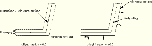
A surface offset is the distance between the midplane of a thin body and its reference plane (defined by the nodal coordinates and element connectivities). It is computed by multiplying the offset fraction (specified as a fraction of the surface thickness) by the surface thickness and the element facet normal. This defines the position of the midsurface and, thus, the position of the body with respect to the reference surface; the coordinates of the nodes on the reference surface are not modified. Surface offsets can be specified only for surfaces defined on shell and similar elements (i.e., membrane, rigid, and surface elements). Surface offsets specified for other elements (e.g., solid or beam elements) will be ignored. By default, surface offsets specified in element section definitions will be used in the general contact algorithm.
The surface offset at each node is the average of the maximum and minimum offsets among the faces connected to the node. The offset at a point within a facet is interpolated from the nodal values. At complex intersections (edges connected to more than two faces) the surface offset is set to zero. Figure 29.3.2–3 shows some examples of the positioning of the contact surface with respect to the reference surface for various combinations of surface offsets. Surface offsets used in the general contact algorithm are constrained to lie between –0.5 and 0.5 of the thickness.
You specify the surface offset as a fraction of the surface thickness. The surface offset fraction can be set equal to the offset fraction used for the surface's parent elements or to a specified value.
| Input File Usage: | Use the following option to use the surface offset fraction from the surface's parent elements (default): |
*SURFACE PROPERTY ASSIGNMENT, PROPERTY=OFFSET FRACTION
surface, ORIGINAL
Use the following option to specify a value for the surface offset fraction: *SURFACE PROPERTY ASSIGNMENT, PROPERTY=OFFSET FRACTION surface, offset The offset can be specified as a value or a label (SPOS or SNEG). Specifying SPOS is equivalent to specifying a value of 0.5; specifying SNEG is equivalent to specifying a value of –0.5. |
| ABAQUS/CAE Usage: | Interaction module: Create Interaction: General contact (Explicit): Surface Properties: Shell/Membrane offset assignments: Edit: Select surface, and click the arrows to transfer surface to list of offset assignments. In the Offset Fraction column, enter ORIGINAL to use the surface offset fraction from the surface's parent elements, enter SPOS to use a surface offset fraction of 0.5, enter SNEG to use a surface offset fraction of –0.5, or enter a value for the surface offset fraction. |
Feature edges of a model are defined on beam and truss elements and edges of faces (perimeter and otherwise) of solid and structural elements. By default, edge-to-edge contact in the general contact algorithm in ABAQUS/Explicit accounts for perimeter edges as well as “contact edges” of beam and truss elements.
You can control which feature edges should be activated in the general contact domain by specifying feature edge criteria. By default, only perimeter edges are activated. Feature edge criteria have no effect on “edges” of beam and truss elements—they are activated by their inclusion in the contact domain.
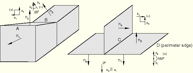
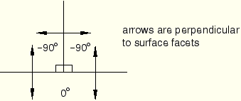
The feature angle is the angle formed between the normals of the two facets connected to an edge. The angles between facets are based on the initial configuration. A negative angle will result at concave meetings of facets; therefore, these edges are never included in the contact domain. Figure 29.3.2–4 shows some examples of how the feature angle is calculated for different edges.
The feature angle for edge A is 90° (the angle betweenFigure 29.3.2–5 Feature angles for a T-intersection (for example, edge C in Figure 29.3.2–4).
The sign of the feature angle is considered when determining whether or not a geometric feature edge should be activated in the general contact domain. For example, if a cutoff feature angle of 20° were specified, edge A would be activated as a feature edge in the contact model (90° > 20°) but edges B and C would not be activated: –25° < 20° and 0° (the maximum feature angle for edge C) < 20°.
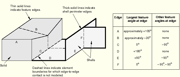
Figure 29.3.2–6 illustrates further how the feature angle is used to determine which geometric feature edges should be activated in the general contact domain.
The table to the right of the figure lists the feature angle values for various edges in the model. Edges connected to more than two facets, as well as edges connected to two shell facets, have more than one corresponding feature angle. The largest feature angle at an edge is compared to the specified cutoff feature angle. For example, if a cutoff feature angle of 20° were specified, edges A, D, and E would be considered feature edges, while edges B, C, and F would be ignored for edge-to-edge contact.By default, only perimeter edges are included in the general contact domain. Perimeter edges occur on “physical” perimeters of shell elements and on “artificial” edges that occur when a subset of exposed facets on a body are included in the general contact domain.
| Input File Usage: | Use the following option to specify that only perimeter edges should be activated in the general contact domain (default): |
*SURFACE PROPERTY ASSIGNMENT, PROPERTY=FEATURE EDGE CRITERIA
surface, PERIMETER EDGES
If the surface name is omitted, a default surface that encompasses the entire general contact domain is assumed. |
| ABAQUS/CAE Usage: | Interaction module: Create Interaction: General contact (Explicit): Surface Properties: Feature edge criteria assignments: Edit: Select surface, click the arrows to transfer surface to list of feature assignments, and enter PERIMETER in the Feature Edge Criteria column. |
You can choose particular feature edges on surface, structural, and rigid elements to be activated in the general contact domain. A surface containing a list of element labels and edge identifiers (see “Defining edge-based surfaces” in “Defining element-based surfaces,” Section 2.3.2) is used to specify the edges to activate.
| Input File Usage: | Use the following option to specify particular feature edges to be activated in the general contact domain: |
*SURFACE PROPERTY ASSIGNMENT, PROPERTY=FEATURE EDGE CRITERIA surface, PICKED EDGES |
You can choose to activate all feature edges in a given surface in the general contact domain. This will activate all edges of every face specified in the given surface.
| Input File Usage: | Use the following option to specify that all feature edges should be activated in the general contact domain: |
*SURFACE PROPERTY ASSIGNMENT, PROPERTY=FEATURE EDGE CRITERIA surface, ALL EDGES |
You can choose to deactivate all feature edges in the general contact domain. This option does not deactivate “contact edges” associated with beam and truss elements.
| Input File Usage: | Use the following option to specify that no feature edges should be activated in the general contact domain: |
*SURFACE PROPERTY ASSIGNMENT, PROPERTY=FEATURE EDGE CRITERIA
surface, NO FEATURE EDGES
If the surface name is omitted, a default surface that encompasses the entire general contact domain is assumed. |
| ABAQUS/CAE Usage: | Interaction module: Create Interaction: General contact (Explicit): Surface Properties: Feature edge criteria assignments: Edit: Select surface, click the arrows to transfer surface to list of feature assignments, and enter NONE in the Feature Edge Criteria column. |
If you specify a cutoff feature angle as the feature edge criteria, perimeter edges and geometric edges with feature angles greater than or equal to the specified angle are activated in the general contact domain. The cutoff feature angle cannot be set to less than 20°. Significant edge-to-edge contact can be enforced for cutoff feature angles of 20° without negatively affecting performance; allowing a cutoff feature angle of less than 20° could severely degrade performance and would not affect the analysis results significantly compared to a cutoff angle of 20°. As described previously, you can activate additional feature edges if needed.
| Input File Usage: | Use the following option to specify a cutoff feature angle (in degrees): |
*SURFACE PROPERTY ASSIGNMENT, PROPERTY=FEATURE EDGE CRITERIA
surface, feature_angle_value
If the surface name is omitted, a default surface that encompasses the entire general contact domain is assumed. |
| ABAQUS/CAE Usage: | Interaction module: Create Interaction: General contact (Explicit): Surface Properties: Feature edge criteria assignments: Edit: Select surface, click the arrows to transfer surface to list of feature assignments, and enter a value for the cutoff feature angle (in degrees) in the Feature Edge Criteria column. |
You can assign a different feature edge criteria to different regions of the general contact domain. For example, the input shown in the following table could be used to specify that none of the feature edges of surf1, only perimeter edges of surf2, and perimeter edges and feature edges of surf3 with a feature angle greater than 30° should be considered for edge-to-edge contact: