Products: ABAQUS/Standard ABAQUS/CAE
Adjusting the position of surfaces in an ABAQUS/Standard contact pair:
can be performed only at the start of a simulation;
causes ABAQUS/Standard to move the nodes of the slave surface so that they precisely contact the master surface (with some exceptions in the case of surface-to-surface discretization);
does not create any strain in the model;
can eliminate small gaps or penetrations caused by numerical roundoff when a graphical preprocessor such as ABAQUS/CAE is used and, thus, prevent possible convergence problems;
is required when two surfaces are tied together for the duration of the analysis;
should not be used to correct gross errors in the mesh design; and
cannot be used with self-contact or symmetric master-slave contact.
will account for shell and membrane thicknesses and shell offsets (these factors are accounted for in the adjustment zone and in the adjustments) for contact formulations other than the default finite-sliding, node-to-surface contact formulation (see “Defining contact pairs in ABAQUS/Standard,” Section 29.2.1).
You can have ABAQUS/Standard adjust the position of the slave surface of a contact pair by specifying either a floating point value a for the depth of an “adjustment zone” around the master surface or a node set label.
By default, ABAQUS/Standard does not adjust the nodes on the slave surface.
The finite-sliding, surface-to-surface contact formulation and the small-sliding, surface-to-surface contact formulation:
will adjust the position of a slave node to achieve a zero gap between the surfaces in an average sense in the region near the slave node, such that the resulting gap may not be exactly zero at the slave node itself; and
will adjust some slave nodes that are outside the adjustment zone if a significant portion of a slave face (or segment in two dimensions) to which it is attached is within the adjustment zone.
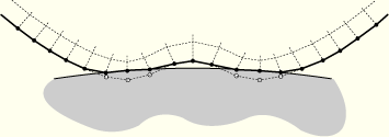
When you specify a, the depth of the “adjustment zone,” ABAQUS/Standard forms an adjustment zone extending a distance a from the master surface. ABAQUS/Standard measures the distance along the master surface normals that pass through the nodes of the slave surface. Any nodes on the slave surface that are within the “adjustment zone” in the initial geometry of the model are moved precisely onto the master surface. The motion of these slave nodes does not create any strain in the model; it is treated as a change in the model definition. An example of adjusting the surfaces of a contact pair is shown in Figure 29.2.5–1 and Figure 29.2.5–2. If you specify a negative value for a, ABAQUS/Standard will issue an error message.
Figure 29.2.5–1 Initial configuration of the contact surfaces showing the “adjustment zone.” The slave surface is in bold.
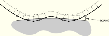
Figure 29.2.5–2 Configuration of the contact surfaces after the adjustment. Nodes within the adjustment zone and overclosed nodes have been moved.
| Input File Usage: | *CONTACT PAIR, ADJUST=a slave_surface, master_surface ... |
| ABAQUS/CAE Usage: | Interaction module: contact interaction editor: Specify tolerance for adjustment zone: a |
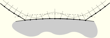
When you specify the depth of the adjustment zone, ABAQUS/Standard moves any slave nodes penetrating the master surface in the initial configuration so that they just contact the master surface. Specifying a value of 0.0 for a causes ABAQUS/Standard to adjust only those slave nodes that are penetrating the master surface. Figure 29.2.5–3 shows the effect of specifying a=0.0 in the example shown in Figure 29.2.5–1. If you do not have ABAQUS/Standard adjust the position of the slave surface, slave nodes that are overclosed in the initial configuration will remain overclosed at the start of the simulation, which may cause convergence problems.
You can specify a node set label instead of an adjustment zone depth when only a subset of the slave nodes should be adjusted and specifying a may cause the inappropriate adjustment of other slave nodes. ABAQUS/Standard adjusts only those nodes on the slave surface belonging to the node set. The node set can contain nodes that are not on the slave surface at all: ABAQUS/Standard will ignore them and adjust only the nodes in the node set that are part of the slave surface.
ABAQUS/Standard moves any slave nodes in the specified node set regardless of how far they are from the master surface. The adjustments of the nodes from their initial configurations do not create strains in the elements forming the slave surface. If ABAQUS/Standard adjusts slave nodes that are far from the master surface, the elements may become poorly shaped, which can cause convergence difficulties.
| Input File Usage: | *CONTACT PAIR, ADJUST=node_set_label slave_surface, master_surface ... |
| ABAQUS/CAE Usage: | Interaction module: contact interaction editor: Adjust slave nodes in set: node_set_label |
Because ABAQUS/Standard adjusts only the slave nodes in the specified node set, any overclosed slave nodes not in the specified node set remain overclosed at the start of the simulation. Using a node set label may, therefore, cause convergence problems if severely overclosed slave nodes, which need to be adjusted, are not included in the node set. This behavior is different from that seen if a is specified, in which case ABAQUS/Standard adjusts all of the overclosed nodes on the slave surface.
There are several instances when adjusting the surfaces in a contact pair is required or strongly recommended:
When tying two surfaces together for the duration of the analysis (see “Defining tied contact in ABAQUS/Standard,” Section 29.2.7).
When using small- or infinitesimal-sliding contact (see “Contact formulation for ABAQUS/Standard contact pairs,” Section 29.2.2).
When specifying a precise initial clearance or initial overclosure for the contact surfaces by defining an allowable contact interference (see “Alternative methods for specifying precise initial clearances or overclosures” below).
You can define precise initial clearance or overclosure values and contact directions for the nodes on the slave surface when they would not be computed accurately enough from the nodal coordinates; for example, if the initial clearance is very small compared to the coordinate values.
The initial clearance or overclosure value calculated at every slave node (based on the coordinates of the slave node and the master surface) is overwritten by the value that you specify. This procedure is performed internally, and it does not affect the coordinates of the slave nodes. If you define a clearance, ABAQUS/Standard will treat the two surfaces as not being in contact, regardless of their nodal coordinates. If you define an overclosure, ABAQUS/Standard will treat the two surfaces as an interference fit and attempt to resolve the overclosure in the first increment. If the defined overclosure is large, you may need to specify an allowable interference that is ramped off over several increments. See “Modeling contact interference fits in ABAQUS/Standard,” Section 29.2.4, for further discussion of interference fits.
You can define initial clearance or overclosure values only for small-sliding contact (“Defining contact pairs in ABAQUS/Standard,” Section 29.2.1). For a technique that can be used to model clearances or overclosures between finite-sliding contact pairs, see “Alternative methods for specifying precise initial clearances or overclosures” below.
You can specify a uniform clearance or overclosure for a contact pair by identifying the master and slave surfaces of the contact pair and the desired initial clearance, ![]() (positive for a clearance; negative for an overclosure). No other data are needed.
(positive for a clearance; negative for an overclosure). No other data are needed.
| Input File Usage: | *CLEARANCE, SLAVE=surface_name, MASTER=surface_name, VALUE= |
| ABAQUS/CAE Usage: | Interaction module: contact interaction editor: Clearance: Initial clearance: Uniform value across slave surface: |
Alternatively, you can specify spatially varying clearances or overclosures for a contact pair by identifying the master and slave surfaces of the contact pair and providing a table of data specifying the clearance at a single node or a set of nodes belonging to the slave surface. Any slave surface node that is not identified will use the clearance that ABAQUS/Standard calculates from the initial geometry of the surfaces.
| Input File Usage: | *CLEARANCE, SLAVE=surface_name, MASTER=surface_name, TABULAR node number or node set label, clearance value |
Repeat the data line as often as necessary. |
| ABAQUS/CAE Usage: | You cannot specify initial clearance or overclosure values using a table of data in ABAQUS/CAE. |
ABAQUS/Standard can read the spatially varying clearances or overclosures for a contact pair from an external file.
| Input File Usage: | *CLEARANCE, SLAVE=surface_name, MASTER=surface_name, TABULAR, INPUT=file_name |
| ABAQUS/CAE Usage: | You cannot specify initial clearance or overclosure values using an external input file in ABAQUS/CAE. |
Normally ABAQUS/Standard calculates the surface normal used for the contact calculations from the geometry of the discretized surfaces, using the algorithms described in “Contact formulation for ABAQUS/Standard contact pairs,” Section 29.2.2. When specifying spatially varying clearances or overclosures, you can redefine the contact direction that ABAQUS/Standard uses with each slave node by specifying the components of this vector. The vector must be defined in the global Cartesian coordinate system, and it should define the master surface's desired outward normal direction.
| Input File Usage: | *CLEARANCE, SLAVE=surface_name, MASTER=surface_name, TABULAR node number or node set label, clearance value, first normal component, second normal component, third normal component |
Repeat the data line as often as necessary. |
| ABAQUS/CAE Usage: | You cannot redefine contact directions in ABAQUS/CAE, except for threaded bolt connections (see “Generating the contact normal directions for a threaded bolt connection automatically” below). |
Alternatively, for a single-threaded bolt connection the contact normal directions for each slave node can be generated automatically by specifying the thread geometry data and two points used to define a vector on the axis of the bolt/bolt hole. The vector should be oriented to point from the tip of the bolt to the head of the bolt when in tension and from the head to the tip when in compression.
| Input File Usage: | *CLEARANCE, SLAVE=surface_name, MASTER=surface_name, TABULAR, BOLT half-thread angle, pitch, major bolt diameter, mean bolt diameter node number or node set label, clearance value, coordinates of points a and b on the axis of the bolt/bolt hole |
Repeat the second data line as often as necessary. |
| ABAQUS/CAE Usage: | Interaction module: contact interaction editor: Clearance: Initial clearance: Computed for single-threaded bolt or Specify for single-threaded bolt: clearance value, Clearance region on slave surface: Edit Region: select region, Bolt direction vector: Edit: select axis, Half-thread angle: half-thread angle, Pitch: pitch, Bolt diameter: Major: major bolt diameter or Mean: mean bolt diameter |
ABAQUS/Standard does not adjust the coordinates of the slave surface when precise initial clearances or overclosures are specified. Therefore, the specified clearances or overclosures cannot be seen in the model in ABAQUS/CAE. Thus, depending on the initial geometry of the surfaces and the magnitude of the clearances or overclosures, the surfaces may appear open or closed in ABAQUS/CAE when they are actually just in contact. However, the actual clearance can be displayed in ABAQUS/CAE by plotting a contour plot of the variable COPEN.
ABAQUS/Standard offers an alternative method of defining precise initial clearances or overclosures that is applicable to both small-sliding and finite-sliding contact pairs. In this method you specify an adjustment zone depth for the contact pair (as described above in “Adjusting the surfaces in a contact pair”) to move the surfaces forming the contact pair exactly into contact at the start of the analysis. Then, in the first step of the simulation you specify an allowable contact interference, ![]() , for the contact pair (see “Modeling contact interference fits in ABAQUS/Standard,” Section 29.2.4). The contact interference definition must refer to an amplitude curve; the form of the amplitude curve depends on whether a clearance or an overclosure is being defined and is described below. The clearance or overclosure will be uniform across the surfaces.
, for the contact pair (see “Modeling contact interference fits in ABAQUS/Standard,” Section 29.2.4). The contact interference definition must refer to an amplitude curve; the form of the amplitude curve depends on whether a clearance or an overclosure is being defined and is described below. The clearance or overclosure will be uniform across the surfaces.
| Input File Usage: | Use all of the following options: |
*CONTACT PAIR, ADJUST=a slave_surface, master_surface *AMPLITUDE, NAME=amplitude_name *CONTACT INTERFERENCE, AMPLITUDE=amplitude_name slave_surface, master_surface, |
| ABAQUS/CAE Usage: | Interaction module: contact interaction editor: Specify tolerance for adjustment zone: a, Interference Fit: toggle on Uniform allowable interference, Amplitude: amplitude_name, Magnitude at start of step: |
To specify a precise clearance by defining an allowable contact interference, the amplitude curve should have a constant magnitude for the duration of the step. A positive value should be given as the allowable interference, ![]() . When viewed in ABAQUS/CAE, these surfaces will appear to penetrate each other when they are in contact. The surfaces start the simulation with coordinates that have them exactly touching, but the specified interference
. When viewed in ABAQUS/CAE, these surfaces will appear to penetrate each other when they are in contact. The surfaces start the simulation with coordinates that have them exactly touching, but the specified interference ![]() makes them behave as if they have a clearance between them.
makes them behave as if they have a clearance between them.
To specify a precise overclosure by defining an allowable contact interference, the amplitude curve should ramp from zero to unity over the duration of the step to allow ABAQUS/Standard to resolve the overclosure gradually. A negative value should be given as the allowable interference, ![]() . When viewed in ABAQUS/CAE, the surfaces start the simulation with coordinates that have them exactly touching, but the specified interference
. When viewed in ABAQUS/CAE, the surfaces start the simulation with coordinates that have them exactly touching, but the specified interference ![]() makes them behave as if they are overclosed. As ABAQUS/Standard resolves the overclosure, these surfaces will appear to separate from each other. When the gap between the two surfaces is equal to a distance of
makes them behave as if they are overclosed. As ABAQUS/Standard resolves the overclosure, these surfaces will appear to separate from each other. When the gap between the two surfaces is equal to a distance of ![]() , the surfaces will behave as if they are precisely in contact.
, the surfaces will behave as if they are precisely in contact.