Product: ABAQUS/Standard
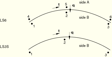
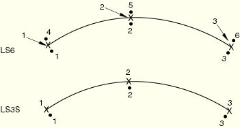
| LS6 | 6-node general second-order line spring |
| LS3S | 3-node second-order line spring for use on a symmetry plane |
X, Y, Z required at each node and, optionally, ![]() ,
, ![]() ,
, ![]() (direction cosines of the normal to the shell) at each node.
(direction cosines of the normal to the shell) at each node.
A user-defined normal definition (see “Normal definitions at nodes,” Section 2.1.4) can also be used to specify ![]() ,
, ![]() ,
, ![]() . If these are not specified, they are constructed as for all other shell elements—by averaging over the shell elements attached to each node.
. If these are not specified, they are constructed as for all other shell elements—by averaging over the shell elements attached to each node.
The only element property used is the thickness; the number of integration points is ignored, since the elements work on the basis of section properties.
| Input File Usage: | Use the following option to define line spring element properties: |
*SHELL SECTION Use the following option to define the depth of the crack as a function of position: *SURFACE FLAW |
Distributed loads are specified as described in “Distributed loads,” Section 27.4.3.
Three Gauss points are used for crack face pressure loading.
Load ID (*DLOAD): HP
Units: FL–2
Description: Hydrostatic surface pressure on the crack faces, with magnitude varying linearly with the global Z-direction.
Load ID (*DLOAD): P
Units: FL–2
Description: Surface pressure on the crack faces.
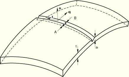
Nodes 1, 2, and 3 on the element define side B and nodes 4, 5, and 6 define side A (see Figure 26.10.2–1). The sign of the crack is defined by the surface of the shell from which the crack originates, which you identify when you define the depth of the crack (see “Line spring elements for modeling part-through cracks in shells,” Section 26.10.1). If the crack originates from the positive surface of the shell, sign(crack)=1.0; if the crack originates from the negative surface of the shell, sign(crack)=–1.0.
The vector ![]() is defined by the right-hand rule from the cross product of the tangent,
is defined by the right-hand rule from the cross product of the tangent, ![]() , which is positive going from node 1 to node 3 of the element, and the normal,
, which is positive going from node 1 to node 3 of the element, and the normal, ![]() , defined when the coordinates are given (or by a user-defined normal definition). For element type LS3S the vector
, defined when the coordinates are given (or by a user-defined normal definition). For element type LS3S the vector ![]() must point into the model (away from the symmetry plane). For element type LS6 the vector
must point into the model (away from the symmetry plane). For element type LS6 the vector ![]() must point from side A to side B.
must point from side A to side B.
E11 | Mode I opening displacement, |
E22 | Mode I opening rotation, |
The following strains exist only for LS6:
E33 | Mode II through thickness shear, |
E12 | Mode II rotation, |
E13 | Mode III anti-plane shear, |
E23 | Mode III opening rotation, |
The conjugate forces and moments are available by requesting “stress” output.
The J-integral is provided at each integration point. If elastic-plastic material behavior is defined, the elastic and plastic parts of J are provided. The stress intensity factors, K, are also provided corresponding to the elastic parts of J.