Products: ABAQUS/Standard ABAQUS/Explicit ABAQUS/CAE
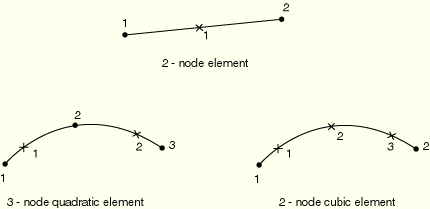
| B21 | 2-node linear beam |
| B21H(S) | 2-node linear beam, hybrid formulation |
| B22 | 3-node quadratic beam |
| B22H(S) | 3-node quadratic beam, hybrid formulation |
| B23(S) | 2-node cubic beam |
| B23H(S) | 2-node cubic beam, hybrid formulation |
| PIPE21(S) | 2-node linear pipe |
| PIPE21H(S) | 2-node linear pipe, hybrid formulation |
| PIPE22(S) | 3-node quadratic pipe |
| PIPE22H(S) | 3-node quadratic pipe, hybrid formulation |
All of the cubic beam elements have two additional variables relating to axial strain.
The linear pipe elements have one additional variable, and the quadratic pipe elements have two additional variables relating to the hoop strain.
The hybrid beam and pipe elements have additional variables relating to the axial force and transverse shear force. The linear elements have two, the quadratic elements have four, and the cubic elements have three additional variables.
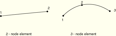
| B31 | 2-node linear beam |
| B31H(S) | 2-node linear beam, hybrid formulation |
| B32 | 3-node quadratic beam |
| B32H(S) | 3-node quadratic beam, hybrid formulation |
| B33(S) | 2-node cubic beam |
| B33H(S) | 2-node cubic beam, hybrid formulation |
| PIPE31(S) | 2-node linear pipe |
| PIPE31H(S) | 2-node linear pipe, hybrid formulation |
| PIPE32(S) | 3-node quadratic pipe |
| PIPE32H(S) | 3-node quadratic pipe, hybrid formulation |
All of the cubic beam elements have two additional variables relating to axial strain.
The linear pipe elements have one additional variable, and the quadratic pipe elements have two additional variables relating to the hoop strain.
The hybrid beam and pipe elements have additional variables relating to the axial force and transverse shear force in the linear and quadratic elements and to the axial force only in the cubic elements. The linear and cubic elements have three and the quadratic elements have six additional variables.
Beams in a plane: X, Y, also (optional) ![]() ,
, ![]() , the direction cosines of the normal.
, the direction cosines of the normal.
Beams in space: X, Y, Z, also (optional) ![]() ,
, ![]() ,
, ![]() , the direction cosines of the second local cross-section axis.
, the direction cosines of the second local cross-section axis.
For PIPE elements use only the pipe section type.
For open-section elements use only the arbitrary, I, L, and linear generalized section types.
Local orientations defined as described in “Orientations,” Section 2.2.5, cannot be used with beam elements to define local material directions. The orientation of the local beam section axes in space is discussed in “Beam element cross-section orientation,” Section 23.3.4.
| Input File Usage: | Use either of the following options: |
*BEAM SECTION *BEAM GENERAL SECTION |
| ABAQUS/CAE Usage: | Property module: Create Section: select Beam as the section Category and Beam as the section Type |
Distributed loads are specified as described in “Distributed loads,” Section 27.4.3.
Load ID (*DLOAD): CENT(S)
ABAQUS/CAE Load/Interaction: Not supported
Units: FL–2 (ML–1T–2)
Description: Centrifugal force (magnitude is input as ![]() , where m is the mass per unit length and
, where m is the mass per unit length and ![]() is the angular velocity).
is the angular velocity).
Load ID (*DLOAD): CENTRIF(S)
ABAQUS/CAE Load/Interaction: Rotational body force
Units: T–2
Description: Centrifugal load (magnitude is input as ![]() , where
, where ![]() is the angular velocity).
is the angular velocity).
Load ID (*DLOAD): CORIO(S)
ABAQUS/CAE Load/Interaction: Not supported
Units: FL–2T (ML–1T–1)
Description: Coriolis force (magnitude is input as ![]() , where m is the mass per unit length and
, where m is the mass per unit length and ![]() is the angular velocity). The load stiffness due to Coriolis loading is not accounted for in direct steady-state dynamics analysis.
is the angular velocity). The load stiffness due to Coriolis loading is not accounted for in direct steady-state dynamics analysis.
Load ID (*DLOAD): GRAV
ABAQUS/CAE Load/Interaction: Gravity
Units: LT–2
Description: Gravity loading in a specified direction (magnitude is input as acceleration).
Load ID (*DLOAD): PX
ABAQUS/CAE Load/Interaction: Line load
Units: FL–1
Description: Force per unit length in global X-direction.
Load ID (*DLOAD): PY
ABAQUS/CAE Load/Interaction: Line load
Units: FL–1
Description: Force per unit length in global Y-direction.
Load ID (*DLOAD): PZ
ABAQUS/CAE Load/Interaction: Line load
Units: FL–1
Description: Force per unit length in global Z-direction (only for beams in space).
Load ID (*DLOAD): PXNU
ABAQUS/CAE Load/Interaction: Line load
Units: FL–1
Description: Nonuniform force per unit length in global X-direction with magnitude supplied via user subroutine DLOAD in ABAQUS/Standard and VDLOAD in ABAQUS/Explicit.
Load ID (*DLOAD): PYNU
ABAQUS/CAE Load/Interaction: Line load
Units: FL–1
Description: Nonuniform force per unit length in global Y-direction with magnitude supplied via user subroutine DLOAD in ABAQUS/Standard and VDLOAD in ABAQUS/Explicit.
Load ID (*DLOAD): PZNU
ABAQUS/CAE Load/Interaction: Line load
Units: FL–1
Description: Nonuniform force per unit length in global Z-direction with magnitude supplied via user subroutine DLOAD in ABAQUS/Standard and VDLOAD in ABAQUS/Explicit. (Only for beams in space.)
Load ID (*DLOAD): P1
ABAQUS/CAE Load/Interaction: Line load
Units: FL–1
Description: Force per unit length in beam local 1-direction (only for beams in space).
Load ID (*DLOAD): P2
ABAQUS/CAE Load/Interaction: Line load
Units: FL–1
Description: Force per unit length in beam local 2-direction.
Load ID (*DLOAD): P1NU
ABAQUS/CAE Load/Interaction: Line load
Units: FL–1
Description: Nonuniform force per unit length in beam local 1-direction with magnitude supplied via user subroutine DLOAD in ABAQUS/Standard and VDLOAD in ABAQUS/Explicit. (Only for beams in space.)
Load ID (*DLOAD): P2NU
ABAQUS/CAE Load/Interaction: Line load
Units: FL–1
Description: Nonuniform force per unit length in beam local 2-direction with magnitude supplied via user subroutine DLOAD in ABAQUS/Standard and VDLOAD in ABAQUS/Explicit.
Load ID (*DLOAD): ROTA(S)
ABAQUS/CAE Load/Interaction: Rotational body force
Units: T–2
Description: Rotary acceleration load (magnitude is input as ![]() , where
, where ![]() is the rotary acceleration).
is the rotary acceleration).
Load ID (*): HPI(S)
ABAQUS/CAE Load/Interaction: Pipe pressure
Units: FL–2
Description: Hydrostatic internal pressure (closed-end condition), varying linearly with the global Z-coordinate.
Load ID (*): HPE(S)
ABAQUS/CAE Load/Interaction: Pipe pressure
Units: FL–2
Description: Hydrostatic external pressure (closed-end condition), varying linearly with the global Z-coordinate.
Load ID (*): PI(S)
ABAQUS/CAE Load/Interaction: Pipe pressure
Units: FL–2
Description: Uniform internal pressure (closed-end condition).
Load ID (*): PE(S)
ABAQUS/CAE Load/Interaction: Pipe pressure
Units: FL–2
Description: Uniform external pressure (closed-end condition).
Load ID (*): PENU(S)
ABAQUS/CAE Load/Interaction: Pipe pressure
Units: FL–2
Description: Nonuniform external pressure (closed-end condition) with magnitude supplied via user subroutine DLOAD.
Load ID (*): PINU(S)
ABAQUS/CAE Load/Interaction: Pipe pressure
Units: FL–2
Description: Nonuniform internal pressure (closed-end condition) with magnitude supplied via user subroutine DLOAD.
ABAQUS/Aqua loads are specified as described in “ABAQUS/Aqua analysis,” Section 6.10.1. They are not available for open-section beams and do not apply to beams that are defined to have additional inertia due to immersion in fluid (see “Additional inertia due to immersion in fluid” in “Beam section behavior,” Section 23.3.5).
Load ID (*CLOAD/ *DLOAD): FDD
ABAQUS/CAE Load/Interaction: Not supported
Units: FL–1
Description: Transverse fluid drag load.
Load ID (*CLOAD/ *DLOAD): FD1
ABAQUS/CAE Load/Interaction: Not supported
Units: F
Description: Fluid drag force on the first end of the beam (node 1).
Load ID (*CLOAD/ *DLOAD): FD2
ABAQUS/CAE Load/Interaction: Not supported
Units: F
Description: Fluid drag force on the second end of the beam (node 2 or node 3).
Load ID (*CLOAD/ *DLOAD): FDT
ABAQUS/CAE Load/Interaction: Not supported
Units: FL–1
Description: Tangential fluid drag load.
Load ID (*CLOAD/ *DLOAD): FI
ABAQUS/CAE Load/Interaction: Not supported
Units: FL–1
Description: Transverse fluid inertia load.
Load ID (*CLOAD/ *DLOAD): FI1
ABAQUS/CAE Load/Interaction: Not supported
Units: F
Description: Fluid inertia force on the first end of the beam (node 1).
Load ID (*CLOAD/ *DLOAD): FI2
ABAQUS/CAE Load/Interaction: Not supported
Units: F
Description: Fluid inertia force on the second end of the beam (node 2 or node 3).
Load ID (*CLOAD/ *DLOAD): PB
ABAQUS/CAE Load/Interaction: Not supported
Units: FL–1
Description: Buoyancy load (closed-end condition).
Load ID (*CLOAD/ *DLOAD): WDD
ABAQUS/CAE Load/Interaction: Not supported
Units: FL–1
Description: Transverse wind drag load.
Load ID (*CLOAD/ *DLOAD): WD1
ABAQUS/CAE Load/Interaction: Not supported
Units: F
Description: Wind drag force on the first end of the beam (node 1).
Load ID (*CLOAD/ *DLOAD): WD2
ABAQUS/CAE Load/Interaction: Not supported
Units: F
Description: Wind drag force on the second end of the beam (node 2 or node 3).
Foundations are available only in ABAQUS/Standard and are specified as described in “Element foundations,” Section 2.2.2.
Load ID (*FOUNDATION): FX(S)
ABAQUS/CAE Load/Interaction: Not supported
Units: FL–2
Description: Stiffness per unit length in global X-direction.
Load ID (*FOUNDATION): FY(S)
ABAQUS/CAE Load/Interaction: Not supported
Units: FL–2
Description: Stiffness per unit length in global Y-direction.
Load ID (*FOUNDATION): FZ(S)
ABAQUS/CAE Load/Interaction: Not supported
Units: FL–2
Description: Stiffness per unit length in global Z-direction (only for beams in space).
Load ID (*FOUNDATION): F1(S)
ABAQUS/CAE Load/Interaction: Not supported
Units: FL–2
Description: Stiffness per unit length in beam local 1-direction (only for beams in space).
Load ID (*FOUNDATION): F2(S)
ABAQUS/CAE Load/Interaction: Not supported
Units: FL–2
Description: Stiffness per unit length in beam local 2-direction.
Surface-based distributed loads are specified as described in “Distributed loads,” Section 27.4.3.
Load ID (*DSLOAD): P
ABAQUS/CAE Load/Interaction: Pressure
Units: FL–1
Description: Force per unit length in beam local 2-direction. The distributed surface force is positive in the direction opposite to the surface normal.
Load ID (*DSLOAD): PNU
ABAQUS/CAE Load/Interaction: Pressure
Units: FL–1
Description: Nonuniform force per unit length in beam local 2-direction with magnitude supplied via user subroutine DLOAD in ABAQUS/Standard and VDLOAD in ABAQUS/Explicit. The distributed surface force is positive in the direction opposite to the surface normal.
Incident wave loading is also available for these elements. See “Acoustic loads,” Section 27.4.5.
See “Beam cross-section library,” Section 23.3.9, for a description of the beam element output locations.
Stress and other tensors (including strain tensors) are available for elements with displacement degrees of freedom. All tensors, except for meshed sections, have the same components. For example, the stress components are as follows:
S11 | Axial stress. |
S22 | Hoop stress (available only for pipe elements). |
S12 | Shear stress caused by torsion (available only for beam-type elements in space). This component is not available when thin-walled, open sections are employed (I-section, L-section, and arbitrary open section). |
S11 | Axial stress. |
S12 | Shear stress along the second cross-section axis caused by shear force and, for beam elements in space, torsion. |
S13 | Shear stress along the first cross-section axis caused by shear force and torsion (available only for beams in space). |
SF1 | Axial force. |
SF2 | Transverse shear force in the local 2-direction (not available for B23, B23H, B33, B33H). |
SF3 | Transverse shear force in the local 1-direction (available only for beams in space, not available for B33, B33H). |
SM1 | Bending moment about the local 1-axis. |
SM2 | Bending moment about the local 2-axis (available only for beams in space). |
SM3 | Twisting moment about the beam axis (available only for beams in space). |
BIMOM | Bimoment due to warping (available only for open-section beams in space). |
ESF1 | Effective axial force for beams subjected to pressure loading (available for all ABAQUS/Standard stress/displacement analysis types except response spectrum and random response). |
See “Beam element formulation,” Section 3.5.2 of the ABAQUS Theory Manual, for the definitions of the section forces and moments.
The effective axial section force for beams subjected to pressure loading is defined as
![]()
For beams that are not subjected to pressure loading, the effective axial force ESF1 is equal to the usual axial force SF1.
SE1 | Axial strain. |
SE2 | Transverse shear strain in the local 2-direction (not available for B23, B23H, B33, and B33H). |
SE3 | Transverse shear strain in the local 1-direction (available only for beams in space, not available for B33 and B33H). |
SK1 | Curvature change about the local 1-axis. |
SK2 | Curvature change about the local 2-axis (available only for beams in space). |
SK3 | Twist of the beam (available only for beams in space). |
BICURV | Bicurvature due to warping (available only for open-section beams in space). |
For beams in space an additional node may be given after a beam element's connectivity (in the element definition—see “Element definition,” Section 2.2.1) to define the approximate direction of the first cross-section axis, ![]() . See “Beam element cross-section orientation,” Section 23.3.4, for details.
. See “Beam element cross-section orientation,” Section 23.3.4, for details.