Products: ABAQUS/Standard ABAQUS/Explicit ABAQUS/CAE
The beam section behavior:
is defined in terms of the response of the beam section to stretching, bending, shear, and torsion;
may or may not require numerical integration over the section; and
can be linear or nonlinear (as a result of nonlinear material response).
Defining a beam section's response to stretching, bending, shear, and torsion of the beam's axis requires a suitable definition of the axial force, N; bending moments, ![]() and
and ![]() ; and torque, T, as functions of the axial strain,
; and torque, T, as functions of the axial strain, ![]() ; curvature changes,
; curvature changes, ![]() and
and ![]() ; and twist,
; and twist, ![]() . Here the subscripts 1 and 2 refer to local, orthogonal axes in the beam section.
. Here the subscripts 1 and 2 refer to local, orthogonal axes in the beam section.
If open-section beam types are used, the section behavior must also define the warping bimoment, W, and the generalized strain measures include the warping amplitude, w, and the bicurvature of the beam, ![]() , which is the gradient of the warping amplitude with respect to position along the beam:
, which is the gradient of the warping amplitude with respect to position along the beam: ![]() .
.
The type of section definition you choose determines whether the beam section properties are recomputed during the progression of the analysis or established in the preprocessor for the duration of the analysis. If a general beam section definition is used (see “Using a general beam section to define the section behavior,” Section 23.3.7), the cross-section properties are computed once, during preprocessing. Alternatively, a beam section definition that is integrated during the analysis can be used (see “Using a beam section integrated during the analysis to define the section behavior,” Section 23.3.6), in which case ABAQUS will use numerical integration of the stress over the cross-section to define the beam's response as the analysis proceeds.
Since planar beams deform only in the X–Y plane, only N and ![]() , and
, and ![]() and
and ![]() , contribute to the response in these elements:
, contribute to the response in these elements: ![]() ,
, ![]() , and w are assumed to be zero.
, and w are assumed to be zero.
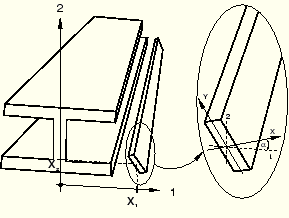
In ABAQUS bending moments in beam sections are always measured about the centroid of the beam section, while torque is measured with respect to the shear center. The beam axis (defined as the line joining the nodes that define the beam element) need not pass through the centroid of the beam section.
The degrees of freedom of the beam element are at the origin of the local ![]() coordinate system defined in the cross-section of the beam; that is, the line of the element connecting the element's nodes passes through the origin of the cross-section's local coordinate system.
coordinate system defined in the cross-section of the beam; that is, the line of the element connecting the element's nodes passes through the origin of the cross-section's local coordinate system.
When a beam section integrated during the analysis is used (see “Using a beam section integrated during the analysis to define the section behavior,” Section 23.3.6), ABAQUS integrates numerically over the section as the beam deforms, evaluating the material behavior independently at each point on the section. This type of beam section should be used when the section nonlinearity is caused only by nonlinear material response.
When a general beam section is used (see “Using a general beam section to define the section behavior,” Section 23.3.7), ABAQUS precomputes the beam cross-section quantities and performs all section computations during the analysis in terms of the precomputed values. This method combines the functions of beam section and material descriptions (a material definition is not needed). The precomputed section properties may be specified in a variety of ways, including quite complex geometries defined with a two-dimensional finite element mesh (see “Meshed beam cross-sections,” Section 10.4.1). A general beam section should be used when the beam section response is linear or when it is nonlinear and the nonlinearity arises from more than just material nonlinearity, such as in cases when section collapse occurs.
| Input File Usage: | Use the following option to define a beam section integrated during the analysis: |
*BEAM SECTION Use the following option to define a general beam section: *BEAM GENERAL SECTION |
The section quantities described below are needed to define the behavior of a general beam section.
The moments of inertia with respect to the centroid are defined as
Bending stiffness contributions for a meshed section profile (see “Meshed cross-sections” in “Choosing a beam cross-section,” Section 23.3.2) are calculated using the two-dimensional cross-section model. The following integrated properties are defined with respect to the centroid for the entire cross-section model meshed with warping elements:
The torsional rigidity, J, depends on the shape of the cross section. The torsional rigidity of a circular section is the polar moment of inertia, ![]() .
.
The torsional rigidity for the rectangular and trapezoidal library sections is calculated numerically by ABAQUS using the Prandtl stress function approach. A local finite element model of the cross-section is created internally for this purpose. The number of integration points selected for the cross-section determines the accuracy of this finite element model. For increased accuracy specify a higher-order rule by selecting nondefault integration.
The above rule is also applied to both the thin-walled box section and the arbitrary section to increase the accuracy of the model. If the thickness for each segment making up the section varies significantly, more integration points for the box section or smaller segments for the arbitrary section should be specified in the area where the thickness varies.
The torsional rigidity for a meshed section is calculated over the two-dimensional region meshed with warping elements. The accuracy of the integration depends on the number of elements in the model:
![]()
For closed thin-walled sections the torsional rigidity is calculated from
![]()
For open, built-up, thin-walled sections,
![]()
In general, the rotary inertia associated with torsional modes is different from that of flexural modes. For unsymmetric cross-sections the rotary inertia is different in each direction of bending. For cross-sections where the beam node is not located at the center of mass, coupling exists between the translational and rotational degrees of freedom.
By default, the exact (anisotropic and coupled) rotary inertia is used for Timoshenko beams. In ABAQUS/Standard the anisotropic rotary inertia introduces unsymmetric terms in the Jacobian operator during geometrically nonlinear, transient, direct-integration dynamic simulations. If the rotary inertia effects are significant in the geometrically nonlinear dynamic response and the exact rotary inertia is used, the unsymmetric solver should be used for better convergence.
Optionally, an approximate isotropic and uncoupled rotary inertia can be selected. In ABAQUS/Standard this means that the rotary inertia associated with the torsional mode only is used for all rotational degrees of freedom; potentially destabilizing rotary inertia effects in impact problems due to the anisotropy or displacement-rotation coupling will not be introduced. In ABAQUS/Explicit this means a scaled flexural inertia with a scaling factor chosen to maximize the stable element time increment is used for all rotational degrees of freedom; i.e., the stable time increment will not be determined by the flexural response of the beam. In some slender beam analyses an isotropic approximation to the rotary inertia may be accurate enough.
If beam elements are used to model plate-type structures in ABAQUS/Explicit (i.e., if the moment of inertia about one section axis of the beam is more than a thousand times greater than the moment of inertia about the other axis), the exact rotary inertia formulation may lead to a sharp cut-back in the stable time increment. In this case it is recommended that you either use the isotropic approximation or alternatively consider modeling the structure with shell elements, which might be better suited to this type of analysis.
For a definition of rotary inertia for the beam's cross-section, see “Mass and inertia for Timoshenko beams,” Section 3.5.5 of the ABAQUS Theory Manual.
| Input File Usage: | Use the following option to specify isotropic rotary inertia for a beam section integrated during the analysis: |
*BEAM SECTION, ROTARY INERTIA=ISOTROPIC Use the following option to specify isotropic rotary inertia for a general beam section: *BEAM GENERAL SECTION, ROTARY INERTIA=ISOTROPIC |
| ABAQUS/CAE Usage: | Isotropic rotary inertia for beam sections is not supported in ABAQUS/CAE. The default exact rotary inertia is always used. |
Additional mass and rotary inertia properties for Timoshenko beams (including PIPE elements) can be defined. This added inertia defined within the cross-section per unit length along the beam contributes to the inertia response of the beam without contributing to the structural stiffness. Additional beam inertia cannot be defined for a section if isotropic rotary inertia is used.
To specify additional beam inertia, you define the mass (per unit length) with the mass center positioned at point ![]() in the local (1, 2) beam cross-section axis system. To include rotary inertia (per unit length), you can also define the angle
in the local (1, 2) beam cross-section axis system. To include rotary inertia (per unit length), you can also define the angle ![]() (in degrees) within the cross-section local (1, 2) system that positions the first axis of the rotary inertia coordinate system
(in degrees) within the cross-section local (1, 2) system that positions the first axis of the rotary inertia coordinate system ![]() relative to the local 1-direction in the beam cross-section axis system. See Figure 23.3.5–1 for an illustration.
relative to the local 1-direction in the beam cross-section axis system. See Figure 23.3.5–1 for an illustration.
The rotary inertia components relative to the rotary inertia coordinate system ![]() are defined as
are defined as
As many point masses and rotary inertia contributions as are needed to define the added inertia can be specified. Mass proportional damping associated with the added inertia can be specified by assigning a value to the mass proportional Rayleigh damping coefficient, ![]() , or the composite damping coefficient,
, or the composite damping coefficient, ![]() . ABAQUS will use the mass weighted average (based on the material damping and the added inertia damping) for the element mass proportional damping.
. ABAQUS will use the mass weighted average (based on the material damping and the added inertia damping) for the element mass proportional damping.
| Input File Usage: | Use the following option in conjunction with the beam section definition to specify additional inertia properties: |
*BEAM ADDED INERTIA, ALPHA= |
| ABAQUS/CAE Usage: | Additional inertia properties are not supported in ABAQUS/CAE. |
When a beam is fully or partially submerged, the effect of the surrounding fluid can be modeled as an additional distributed inertia on the beam (see “Loading due to an incident dilatational wave field,” Section 6.3.1 of the ABAQUS Theory Manual). By default, the beam is assumed to be fully submerged. Alternatively, you can specify that the added inertia per unit length should be reduced by a factor of one-half to model a partially submerged beam.
You specify the fluid mass density, ![]() (per unit volume); beam local x and y coordinates of the wetted cross-section centroid; wetted section effective radius, r; and empirical drag or flow coefficients,
(per unit volume); beam local x and y coordinates of the wetted cross-section centroid; wetted section effective radius, r; and empirical drag or flow coefficients, ![]() and
and ![]() . The inertia added per unit length to a fully immersed beam cross-section is given by
. The inertia added per unit length to a fully immersed beam cross-section is given by
![]()
An immersed beam also experiences an additional added mass effect at its free ends. If a beam element's end node is not attached to any other element and additional fluid inertia is defined for this element, an additional mass is added automatically:
![]()
| Input File Usage: | Use the following option in conjunction with the beam section definition to define a fully immersed beam: |
*BEAM FLUID INERTIA, FULL Use the following option in conjunction with the beam section definition to define a partially immersed beam: *BEAM FLUID INERTIA, HALF |
| ABAQUS/CAE Usage: | Immersed beams are not supported in ABAQUS/CAE. |