
Products: ABAQUS/Standard ABAQUS/Explicit ABAQUS/CAE
Truss elements:
are long, slender structural members that can transmit only axial force (nonstructural link elements are presented in “One-dimensional solid (link) element library,” Section 22.1.2); and
do not transmit moments.
Truss elements are used in two and three dimensions to model slender, line-like structures that support loading only along the axis or the centerline of the element. No moments or forces perpendicular to the centerline are supported.
The two-dimensional truss elements can be used in axisymmetric models to represent components, such as bolts or connectors, where the strain is computed from the change in length in the r–z plane only. Two-dimensional trusses can also be used to define master surfaces for contact applications in ABAQUS/Standard (see “Contact interaction analysis: overview,” Section 29.1.1). In this case the direction of the master surface's outward normal is critical for proper detection of contact.
The 3-node truss element available in ABAQUS/Standard is often useful for modeling curved reinforcing cables in structures, such as prestressed tendons in reinforced concrete or long slender pipelines used in the off-shore industry.
A 2-node straight truss element, which uses linear interpolation for position and displacement and has a constant stress, is available in both ABAQUS/Standard and ABAQUS/Explicit. In addition, a 3-node curved truss element, which uses quadratic interpolation for position and displacement so that the strain varies linearly along the element, is available in ABAQUS/Standard.
Hybrid versions of the stress/displacement trusses, coupled temperature-displacement trusses, and piezoelectric trusses are available in ABAQUS/Standard.
Hybrid (mixed) versions of the stress/displacement trusses, in which the axial force is treated as an additional unknown, are available in two and three dimensions in ABAQUS/Standard. These elements are useful (to offset the effects of numerical ill-conditioning on governing equations) when a truss represents a very rigid link whose stiffness is much larger than that of the overall structural model. In such a case a hybrid truss provides an alternative to a truly rigid link, modeled with multi-point constraints (see “General multi-point constraints,” Section 28.2.2) or rigid elements (see “Rigid elements,” Section 24.3.1).
Coupled temperature-displacement truss elements are available in two and three dimensions in ABAQUS/Standard. These elements have temperature as an additional degree of freedom (11). See “Fully coupled thermal-stress analysis,” Section 6.5.4, for information about fully coupled temperature-displacement analysis in ABAQUS/Standard.
Piezoelectric truss elements are available in two and three dimensions in ABAQUS/Standard. These elements have electric potential as an additional degree of freedom (9). See “Piezoelectric analysis,” Section 6.6.3, for information about piezoelectric analysis.
Truss elements in ABAQUS are named as follows:
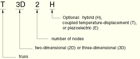
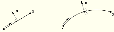
For two-dimensional trusses the positive outward normal, ![]() , is defined by a 90° counterclockwise rotation from the direction going from node 1 to node 2 or node 3 of the element, as shown.
, is defined by a 90° counterclockwise rotation from the direction going from node 1 to node 2 or node 3 of the element, as shown.
You use a solid section definition to define the section properties. You must associate these properties with a region of your model.
| Input File Usage: | *SOLID SECTION, ELSET=name |
where the ELSET parameter refers to a set of truss elements. |
| ABAQUS/CAE Usage: | Property module:
Create Section: select Beam as the section Category and Truss as the
section Type |
You can define the cross-sectional area associated with the truss element as part of the section definition. If you do not specify a value for the cross-sectional area, unit area is assumed.
When truss elements are used in large-displacement analysis, the updated cross-sectional area is calculated by assuming that the truss is made of an incompressible material, regardless of the actual material definition. This assumption affects cases only where the strains are large. It is adopted because the most common applications of trusses at large strains involve yielding metal behavior or rubber elasticity, in which cases the material is effectively incompressible. Therefore, a linear elastic truss element does not provide the same force-displacement response as a linear SPRINGA spring element when the axial strain is not infinitesimal.
| Input File Usage: | *SOLID SECTION, ELSET=name cross-sectional area |
| ABAQUS/CAE Usage: | Property module: Create Section: select Beam as the section Category and Truss as the section Type: Cross-sectional area: cross-sectional area |
You must associate a material definition with each solid section definition. No material orientation is permitted with truss elements.
| Input File Usage: | *SOLID SECTION, MATERIAL=name |
Any value given to the ORIENTATION parameter on the *SOLID SECTION option will be ignored by truss elements. |
| ABAQUS/CAE Usage: | Property module: Create Section: select Beam as the section Category and Truss as the section Type: Material: name |
Truss elements have no initial stiffness to resist loading perpendicular to their axis. If a stress-free line of trusses is loaded perpendicular to its axis in ABAQUS/Standard, numerical singularities and lack of convergence can result. After the first iteration in a large-displacement implicit analysis, stiffness perpendicular to the initial line of the elements develops, sometimes allowing an analysis to overcome numerical problems.
In some cases loading the truss elements along their axis first or including initial tensile stress can overcome these numerical singularities. However, you must choose the magnitude of the loading or initial stress such that the final solution is unaffected.