Products: ABAQUS/Standard ABAQUS/CAE
For structural link (truss) elements, refer to “Truss elements,” Section 23.2.1.
You must provide the cross-sectional area of the element; by default, unit area is assumed.
| Input File Usage: | *SOLID SECTION |
| ABAQUS/CAE Usage: | Property module: Create Section: select Solid as the section Category and Homogeneous as the section Type |
Distributed heat fluxes are available for elements with temperature degrees of freedom. They are specified as described in “Thermal loads,” Section 27.4.4.
Load ID (*DFLUX): BF
ABAQUS/CAE Load/Interaction: Body heat flux
Units: JL–3 T–1
Description: Heat body flux per unit volume.
Load ID (*DFLUX): BFNU
ABAQUS/CAE Load/Interaction: Body heat flux
Units: JL–3 T–1
Description: Nonuniform heat body flux per unit volume with magnitude supplied via user subroutine DFLUX.
Load ID (*DFLUX): S1
ABAQUS/CAE Load/Interaction: Not supported
Units: JL–2 T–1
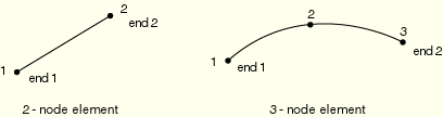
Description: Heat surface flux per unit area into the first end of the link (node 1).
Load ID (*DFLUX): S2
ABAQUS/CAE Load/Interaction: Not supported
Units: JL–2 T–1
Description: Heat surface flux per unit area into the second end of the link (node 2 or node 3).
Load ID (*DFLUX): S1NU
ABAQUS/CAE Load/Interaction: Not supported
Units: JL–2 T–1
Description: Nonuniform heat surface flux per unit area into the first end of the link (node 1) with magnitude supplied via user subroutine DFLUX.
Load ID (*DFLUX): S2NU
ABAQUS/CAE Load/Interaction: Not supported
Units: JL–2 T–1
Description: Nonuniform heat surface flux per unit area into the second end of the link (node 2 or node 3) with magnitude supplied via user subroutine DFLUX.
Film conditions are available for elements with temperature degrees of freedom. They are specified as described in “Thermal loads,” Section 27.4.4.
Load ID (*FILM): F1
ABAQUS/CAE Load/Interaction: Not supported
Units: JL–2T–1![]() –1
–1
Description: Film coefficient and sink temperature (units of ![]() ) at the first end of the link (node 1).
) at the first end of the link (node 1).
Load ID (*FILM): F2
ABAQUS/CAE Load/Interaction: Not supported
Units: JL–2T–1![]() –1
–1
Description: Film coefficient and sink temperature (units of ![]() ) at the second end of the link (node 2 or node 3).
) at the second end of the link (node 2 or node 3).
Load ID (*FILM): F1NU
ABAQUS/CAE Load/Interaction: Not supported
Units: JL–2T–1![]() –1
–1
Description: Nonuniform film coefficient and sink temperature (units of ![]() ) at the first end of the link (node 1) with magnitude supplied via user subroutine FILM.
) at the first end of the link (node 1) with magnitude supplied via user subroutine FILM.
Load ID (*FILM): F2NU
ABAQUS/CAE Load/Interaction: Not supported
Units: JL–2T–1![]() –1
–1
Description: Nonuniform film coefficient and sink temperature (units of ![]() ) at the second end of the link (node 2 or node 3) with magnitude supplied via user subroutine FILM.
) at the second end of the link (node 2 or node 3) with magnitude supplied via user subroutine FILM.
Radiation conditions are available for elements with temperature degrees of freedom. They are specified as described in “Thermal loads,” Section 27.4.4.
Load ID (*RADIATE): R1
ABAQUS/CAE Load/Interaction: Not supported
Units: Dimensionless
Description: Emissivity and sink temperature (units of ![]() ) at the first end of the link (node 1).
) at the first end of the link (node 1).
Load ID (*RADIATE): R2
ABAQUS/CAE Load/Interaction: Not supported
Units: Dimensionless
Description: Emissivity and sink temperature (units of ![]() ) at the second end of the link (node 2 or node 3).
) at the second end of the link (node 2 or node 3).
Distributed impedances are available for elements with acoustic pressure degrees of freedom. They are specified as described in “Acoustic loads,” Section 27.4.5.
Load ID (*IMPEDANCE): I1
ABAQUS/CAE Load/Interaction: Not supported
Units: None
Description: Name of the impedance property that defines the impedance at the first end of the link (node 1).
Load ID (*IMPEDANCE): I2
ABAQUS/CAE Load/Interaction: Not supported
Units: None
Description: Name of the impedance property that defines the impedance at the second end of the link (node 2 or node 3).
Distributed electric current densities are available for coupled thermal-electrical elements. They are specified as described in “Coupled thermal-electrical analysis,” Section 6.6.2.
Load ID (*DECURRENT): CBF
ABAQUS/CAE Load/Interaction: Body current
Units: CL–3T–1
Description: Volumetric current source density.
Load ID (*DECURRENT): CS1
ABAQUS/CAE Load/Interaction: Surface current
Units: CL–2T–1
Description: Current density at the first end of the link (node 1).
Load ID (*DECURRENT): CS2
ABAQUS/CAE Load/Interaction: Surface current
Units: CL–2T–1
Description: Current density at the second end of the link (node 2 or node 3).