Products: ABAQUS/Standard ABAQUS/Explicit ABAQUS/CAE
Rigid elements:
can be used to define the surfaces of rigid bodies for contact;
can be used to define rigid bodies for multibody dynamic simulations;
can be attached to deformable elements;
can be used to constrain parts of a model;
are used to apply ABAQUS/Aqua loads to rigid structures; and
are associated with a given rigid body and share a common node known as the rigid body reference node.
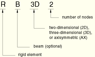
Use R2D2 elements in plane strain or plane stress analysis, RAX2 elements in axisymmetric planar geometries, and R3D3 and R3D4 elements in three-dimensional analysis.
RB2D2 and RB3D2 elements are often used in ABAQUS/Standard to model offshore structures that will transmit ABAQUS/Aqua loads but will not deform. They can also be used as rigid links between nodes on deformable bodies.
Rigid elements in ABAQUS are named as follows:
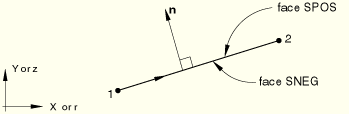
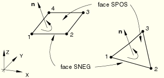
For all rigid elements the face on the side of the element with the positive outward normal is referred to as SPOS. The face on the opposite side is referred to as SNEG. The positive normal direction for each element is defined below.
R2D2, RAX2, RB2D2, R3D3, and R3D4 rigid elements can be used in ABAQUS/Standard to define master surfaces for contact applications. The direction of the master surface's outward normal is critical for proper detection of contact. See “Defining contact pairs in ABAQUS/Standard,” Section 29.2.1, for a more detailed discussion of contact surface definitions.
The positive outward normal direction, ![]() , is defined by a 90° counterclockwise rotation from the direction going from node 1 to node 2 of the element. See Figure 24.3.1–1.
, is defined by a 90° counterclockwise rotation from the direction going from node 1 to node 2 of the element. See Figure 24.3.1–1.
The positive normal for R3D3 and R3D4 elements is given by the right-hand rule going around the nodes of the element in the order that they are given in the element's connectivity. See Figure 24.3.1–2.
RB3D2 elements do not have a unique normal definition.
Rigid elements must always be part of a rigid body. See “Rigid body definition,” Section 2.4.1, for complete details on the definition of a rigid body.
| Input File Usage: | *RIGID BODY, ELSET=name |
where the ELSET parameter refers to a set of rigid elements. |
| ABAQUS/CAE Usage: | Interaction module: Create Constraint: Rigid body: Body (elements) |
In ABAQUS/Standard rigid elements do not contribute mass to the rigid body to which they are assigned. The mass distribution on the rigid surface can be accounted for by using point mass (“Point masses,” Section 24.1.1) and rotary inertia elements (“Rotary inertia,” Section 24.2.1) on the nodes connected to the rigid elements.
By default in ABAQUS/Explicit, rigid elements do not contribute mass to the rigid body to which they are assigned. To define the mass distribution, you can specify the density of all rigid elements in a rigid body. When a nonzero density and thickness are specified, mass and rotary inertia contributions to the rigid body from rigid elements will be computed in an analogous manner to structural elements.
| Input File Usage: | Use the following option in ABAQUS/Explicit to specify the density of rigid elements: |
*RIGID BODY, DENSITY=density |
| ABAQUS/CAE Usage: | You cannot specify the density of rigid elements in ABAQUS/CAE. |
In ABAQUS/Explicit you can specify the cross-sectional area or thickness for all of the rigid elements that are part of a rigid body. ABAQUS/Explicit assumes a default zero cross-sectional area or thickness if you do not specify one.
To account for a continuously varying thickness of a surface formed by rigid elements in ABAQUS/Explicit, you can specify the thickness of the rigid elements at the nodes.
Specifying a nonzero thickness for rigid elements that form a rigid surface in a contact pair definition can be used to account for the effect of surface thickness in the contact constraint. It also enables the use of the double-sided surface contact feature with rigid surfaces formed by rigid elements.
| Input File Usage: | Use the following option in ABAQUS/Explicit to specify the cross-sectional area or thickness for all rigid elements in a rigid body: |
*RIGID BODY
cross-sectional area or thickness
Use both of the following options to specify a continuously varying thickness for a surface formed by rigid elements: *NODAL THICKNESS *RIGID BODY, NODAL THICKNESS |
| ABAQUS/CAE Usage: | You cannot specify the cross-sectional area or thickness of rigid elements in ABAQUS/CAE. |
In ABAQUS/Explicit you can define the distance (measured as a fraction of the rigid element's thickness) from the rigid element's midsurface to the reference surface containing the element's nodes. The positive values of the offset are in the direction of the element normal. When the offset distance is 0.5, the top surface is the reference surface. When the offset distance is –0.5, the bottom surface is the reference surface. The default offset distance is 0, which indicates that the middle surface of the rigid element is the reference surface. You can specify a value for the offset distance that is greater in magnitude than half the rigid element's thickness.
Since no element-level calculations are performed for rigid elements, a specified offset affects only the handling of contact pairs with rigid surfaces formed by rigid elements (see “Defining element-based surfaces,” Section 2.3.2). Mass and rotary inertia contributions to the rigid body from rigid elements defined with an offset are computed as if the offset is zero.
| Input File Usage: | Use the following option in ABAQUS/Explicit to specify a surface offset for a rigid element: |
*RIGID BODY, OFFSET=offset The OFFSET parameter accepts a value or a label (SPOS or SNEG). Specifying SPOS is equivalent to specifying a value of 0.5; specifying SNEG is equivalent to specifying a value of –0.5. |
| ABAQUS/CAE Usage: | You cannot specify an offset for rigid elements in ABAQUS/CAE. |