Products: ABAQUS/Explicit ABAQUS/CAE
The damage evolution capability for ductile metals:
assumes that damage is characterized by the progressive degradation of the material stiffness, leading to material failure;
must be used in combination with a damage initiation criterion for ductile metals (“Damage initiation for ductile metals,” Section 19.2.2);
uses mesh-independent measures (either plastic displacement or physical energy dissipation) to drive the evolution of damage after damage initiation;
takes into account the combined effect of different damage mechanisms acting simultaneously on the same material and includes options to specify how each mechanism contributes to the overall material degradation; and
offers options for what occurs upon failure, including the removal of elements from the mesh.
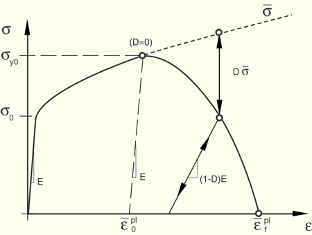
Figure 19.2.3–1 illustrates the characteristic stress-strain behavior of a material undergoing damage. In the context of an elastic-plastic material with isotropic hardening, the damage manifests itself in two forms: softening of the yield stress and degradation of the elasticity. The solid curve in the figure represents the damaged stress-strain response, while the dashed curve is the response in the absence of damage. As discussed later, the damaged response depends on the element dimensions such that mesh dependency of the results is minimized.
In the figure ![]() and
and ![]() are the yield stress and equivalent plastic strain at the onset of damage, and
are the yield stress and equivalent plastic strain at the onset of damage, and ![]() is the equivalent plastic strain at failure; that is, when the overall damage variable reaches the value
is the equivalent plastic strain at failure; that is, when the overall damage variable reaches the value ![]() . The overall damage variable, D, captures the combined effect of all active damage mechanisms and is computed in terms of the individual damage variables,
. The overall damage variable, D, captures the combined effect of all active damage mechanisms and is computed in terms of the individual damage variables, ![]() , as discussed later in this section (see “Evaluating overall damage when multiple criteria are active”).
, as discussed later in this section (see “Evaluating overall damage when multiple criteria are active”).
The value of the equivalent plastic strain at failure, ![]() , depends on the characteristic length of the element and cannot be used as a material parameter for the specification of the damage evolution law. Instead, the damage evolution law is specified in terms of equivalent plastic displacement,
, depends on the characteristic length of the element and cannot be used as a material parameter for the specification of the damage evolution law. Instead, the damage evolution law is specified in terms of equivalent plastic displacement, ![]() , or in terms of fracture energy dissipation,
, or in terms of fracture energy dissipation, ![]() ; these concepts are defined next.
; these concepts are defined next.
When material damage occurs, the stress-strain relationship no longer accurately represents the material's behavior. Continuing to use the stress-strain relation introduces a strong mesh dependency based on strain localization, such that the energy dissipated decreases as the mesh is refined. A different approach is required to follow the strain-softening branch of the stress-strain response curve. Hillerborg's (1976) fracture energy proposal is used to reduce mesh dependency by creating a stress-displacement response after damage is initiated. Using brittle fracture concepts, Hillerborg defines the energy required to open a unit area of crack, ![]() , as a material parameter. With this approach, the softening response after damage initiation is characterized by a stress-displacement response rather than a stress-strain response.
, as a material parameter. With this approach, the softening response after damage initiation is characterized by a stress-displacement response rather than a stress-strain response.
The implementation of this stress-displacement concept in a finite element model requires the definition of a characteristic length, L, associated with an integration point. The fracture energy is then given as
The definition of the characteristic length is based on the element geometry: for beams and trusses we use the integration point length; for shell and planar elements we use the square root of the integration point area; for solid elements we use the cube root of the integration point volume. This definition of the characteristic length is used because the direction in which fracture occurs is not known in advance. Therefore, elements with large aspect ratios will have rather different behavior depending on the direction in which they crack: some mesh sensitivity remains because of this effect, and elements that have aspect ratios close to unity are recommended.
Each damage initiation criterion described in “Damage initiation for ductile metals,” Section 19.2.2, may have an associated damage evolution law. The damage evolution law can be specified in terms of equivalent plastic displacement, ![]() , or in terms of fracture energy dissipation,
, or in terms of fracture energy dissipation, ![]() . Both of these options take into account the characteristic length of the element to alleviate mesh dependency of the results.
. Both of these options take into account the characteristic length of the element to alleviate mesh dependency of the results.
The overall damage variable, D, captures the combined effect of all active mechanisms and is computed in terms of individual damage variables, ![]() , for each mechanism. You can choose to combine some of the damage variables in a multiplicative sense to form an intermediate variable,
, for each mechanism. You can choose to combine some of the damage variables in a multiplicative sense to form an intermediate variable, ![]() , as follows:
, as follows:
![]()
![]()
| Input File Usage: | Use the following option to specify that the damage associated with a particular criterion contributes to the overall damage variable in a maximum sense (default): |
*DAMAGE EVOLUTION, DEGRADATION=MAXIMUM Use the following option to specify that the damage associated with a particular criterion contributes to the overall damage variable in a multiplicative sense: *DAMAGE EVOLUTION, DEGRADATION=MULTIPLICATIVE |
| ABAQUS/CAE Usage: | Use the following options to specify that the damage associated with a particular criterion contributes to the overall damage variable in a maximum sense (default) or in a multiplicative sense, respectively: |
Property module: material editor: Mechanical |
As discussed previously, once the damage initiation criterion has been reached, the effective plastic displacement, ![]() , is defined with the evolution equation
, is defined with the evolution equation
![]()
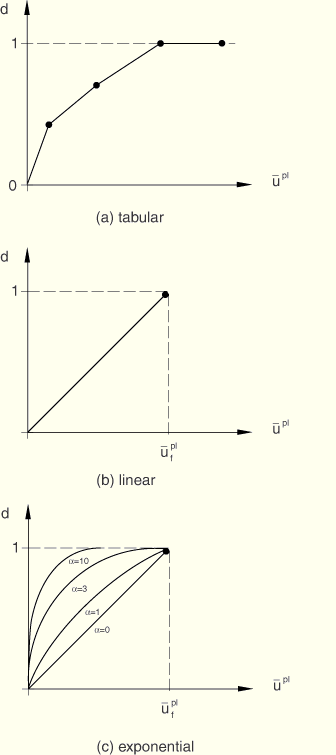
The evolution of the damage variable with the relative plastic displacement can be specified in tabular, linear, or exponential form. Instantaneous failure will occur if the plastic displacement at failure, ![]() , is specified as 0; however, this choice is not recommended and should be used with care because it causes a sudden drop of the stress at the material point that can lead to dynamic instabilities.
, is specified as 0; however, this choice is not recommended and should be used with care because it causes a sudden drop of the stress at the material point that can lead to dynamic instabilities.
You can specify the damage variable directly as a tabular function of equivalent plastic displacement, ![]() , as shown in Figure 19.2.3–2(a).
, as shown in Figure 19.2.3–2(a).
| Input File Usage: | *DAMAGE EVOLUTION, TYPE=DISPLACEMENT, SOFTENING=TABULAR |
| ABAQUS/CAE Usage: | Property module: material editor: Mechanical |
Assume a linear evolution of the damage variable with effective plastic displacement, as shown in Figure 19.2.3–2(b). You can specify the effective plastic displacement, ![]() , at the point of failure (full degradation). Then, the damage variable increases according to
, at the point of failure (full degradation). Then, the damage variable increases according to

| Input File Usage: | *DAMAGE EVOLUTION, TYPE=DISPLACEMENT, SOFTENING=LINEAR |
| ABAQUS/CAE Usage: | Property module: material editor: Mechanical |
Assume an exponential evolution of the damage variable with plastic displacement, as shown in Figure 19.2.3–2(c). You can specify the relative plastic displacement at failure, ![]() , and the exponent
, and the exponent ![]() . The damage variable is given as
. The damage variable is given as
![]()
| Input File Usage: | *DAMAGE EVOLUTION, TYPE=DISPLACEMENT, SOFTENING=EXPONENTIAL |
| ABAQUS/CAE Usage: | Property module: material editor: Mechanical |
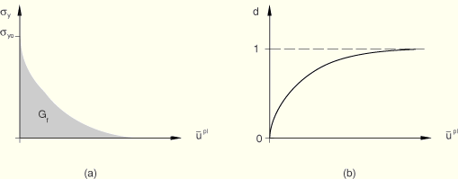
You can specify the fracture energy per unit area, ![]() , to be dissipated during the damage process directly. Instantaneous failure will occur if
, to be dissipated during the damage process directly. Instantaneous failure will occur if ![]() is specified as 0. However, this choice is not recommended and should be used with care because it causes a sudden drop in the stress at the material point that can lead to dynamic instabilities.
is specified as 0. However, this choice is not recommended and should be used with care because it causes a sudden drop in the stress at the material point that can lead to dynamic instabilities.
The evolution in the damage can be specified in linear or exponential form.
Assume a linear evolution of the damage variable with plastic displacement. You can specify the fracture energy per unit area, ![]() . Then, once the damage initiation criterion is met, the damage variable increases according to
. Then, once the damage initiation criterion is met, the damage variable increases according to
![]()
| Input File Usage: | *DAMAGE EVOLUTION, TYPE=ENERGY, SOFTENING=LINEAR |
| ABAQUS/CAE Usage: | Property module: material editor: Mechanical |
Assume an exponential evolution of the damage variable given as
| Input File Usage: | *DAMAGE EVOLUTION, TYPE=ENERGY, SOFTENING=EXPONENTIAL |
| ABAQUS/CAE Usage: | Property module: material editor: Mechanical |
You have control over how ABAQUS treats elements with severe damage. You can specify an upper bound, ![]() , to the overall damage variable, D; and you can choose whether to delete an element once maximum degradation is reached. The latter choice also affects which stiffness components are damaged.
, to the overall damage variable, D; and you can choose whether to delete an element once maximum degradation is reached. The latter choice also affects which stiffness components are damaged.
The default setting of ![]() depends on whether elements are to be deleted upon reaching maximum degradation (discussed next). For the default case of element deletion and in all cases for cohesive elements,
depends on whether elements are to be deleted upon reaching maximum degradation (discussed next). For the default case of element deletion and in all cases for cohesive elements, ![]() ; otherwise,
; otherwise, ![]() . The output variable SDEG contains the value of D. No further damage is accumulated at an integration point once D reaches
. The output variable SDEG contains the value of D. No further damage is accumulated at an integration point once D reaches ![]() (except, of course, any remaining stiffness is lost upon element deletion).
(except, of course, any remaining stiffness is lost upon element deletion).
| Input File Usage: | Use the following option to specify |
*SECTION CONTROLS, MAX DEGRADATION= |
Elements are deleted by default upon reaching maximum degradation. Except for cohesive elements with traction-separation response (see “Defining the constitutive response of cohesive elements using a traction-separation description,” Section 26.5.6), ABAQUS/Explicit applies damage to all stiffness components equally for elements that may eventually be removed:
![]()
An element is removed from the mesh if D reaches ![]() at all of the section points at any one integration location of an element except for cohesive elements (for cohesive elements the conditions for element deletion are that D reaches
at all of the section points at any one integration location of an element except for cohesive elements (for cohesive elements the conditions for element deletion are that D reaches ![]() at all integration points and, for traction-separation response, none of the integration points are in compression). For example, removal of a first-order reduced-integration solid element takes place, by default, when maximum degradation is reached at the only integration point. However, in a shell element all through-the-thickness section points must fail before the element is removed from the mesh. In the case of second-order reduced-integration beam elements, reaching maximum degradation at all section points through the thickness at either of the two element integration locations along the beam axis leads, by default, to element removal. Similarly, in modified triangular and tetrahedral solid elements and fully integrated membrane elements D reaching
at all integration points and, for traction-separation response, none of the integration points are in compression). For example, removal of a first-order reduced-integration solid element takes place, by default, when maximum degradation is reached at the only integration point. However, in a shell element all through-the-thickness section points must fail before the element is removed from the mesh. In the case of second-order reduced-integration beam elements, reaching maximum degradation at all section points through the thickness at either of the two element integration locations along the beam axis leads, by default, to element removal. Similarly, in modified triangular and tetrahedral solid elements and fully integrated membrane elements D reaching ![]() at any one integration point leads, by default, to element removal.
at any one integration point leads, by default, to element removal.
In a heat transfer analysis the thermal properties of the material are not affected by the progressive damage of the material stiffness until the condition for element deletion is reached; at this point the thermal contribution of the element is also removed.
| Input File Usage: | Use the following option to delete the element from the mesh (default): |
*SECTION CONTROLS, ELEMENT DELETION=YES |
Optionally, you may choose not to remove the element from the mesh, except in the case of three-dimensional beam elements. With element deletion turned off, the overall damage variable is enforced to be ![]() . The default value is
. The default value is ![]() if element deletion is turned off, which ensures that elements will remain active in the simulation with a residual stiffness of at least 1% of the original stiffness. The dimensionality of the stress state of the element affects which stiffness components can become damaged, as discussed below.
if element deletion is turned off, which ensures that elements will remain active in the simulation with a residual stiffness of at least 1% of the original stiffness. The dimensionality of the stress state of the element affects which stiffness components can become damaged, as discussed below.
In a heat transfer analysis the thermal properties of the material are not affected by damage of the material stiffness.
| Input File Usage: | Use the following option to keep the element in the computation: |
*SECTION CONTROLS, ELEMENT DELETION=NO |
For elements with three-dimensional stress states (including generalized plane strain elements) the shear stiffness will be degraded up to a maximum value, ![]() , leading to softening of the deviatoric stress components. The bulk stiffness, however, will be degraded only while the material is subjected to negative pressures (i.e., hydrostatic tension); there is no bulk degradation under positive pressures. This corresponds to a fluid-like behavior. Therefore, the degraded deviatoric,
, leading to softening of the deviatoric stress components. The bulk stiffness, however, will be degraded only while the material is subjected to negative pressures (i.e., hydrostatic tension); there is no bulk degradation under positive pressures. This corresponds to a fluid-like behavior. Therefore, the degraded deviatoric, ![]() , and pressure, p, stresses are computed as
, and pressure, p, stresses are computed as
![]()
For elements with a plane stress formulation (plane stress, shell, continuum shell, and membrane elements) the stiffness will be degraded uniformly until the maximum degradation, ![]() , is reached. Output variable SDEG contains the value of D.
, is reached. Output variable SDEG contains the value of D.
For elements with a one-dimensional stress state (i.e., truss elements, rebar, and cohesive elements with gasket behavior) their only stress component will be degraded if it is positive (tension). The material stiffness will remain unaffected under compression loading. The stress is, therefore, given by ![]() , where the uniaxial damage variable is computed as
, where the uniaxial damage variable is computed as
It is possible to use material damage models in elements for which rebar are also defined. The base material contribution to the element stress-carrying capacity diminishes according to the behavior described previously in this section. The rebar contribution to the element stress-carrying capacity will not be affected unless damage is also included in the rebar material definition; in that case the rebar contribution to the element stress-carrying capacity will also be degraded after the damage initiation criterion specified for the rebar is met. For the default choice of element deletion, the element is removed from the mesh when at any one integration location all section points in the base material and rebar are fully degraded.
Damage evolution for ductile metals can be defined for any element that can be used with the damage initiation criteria for ductile metals in ABAQUS/Explicit (“Damage initiation for ductile metals,” Section 19.2.2).
In addition to the standard output identifiers available in ABAQUS/Explicit (“ABAQUS/Explicit output variable identifiers,” Section 4.2.2), the following variables have special meaning when damage evolution is specified:
STATUS | Status of element (the status of an element is 1.0 if the element is active, 0.0 if the element is not). |
SDEG | Overall scalar stiffness degradation, D. |