Products: ABAQUS/Standard ABAQUS/Explicit ABAQUS/CAE
The porous metal plasticity model:
is used to model materials with a dilute concentration of voids in which the relative density is greater than 0.9;
is based on Gurson's porous metal plasticity theory (Gurson, 1977) with void nucleation and, in ABAQUS/Explicit, a failure definition; and
defines the inelastic flow of the porous metal on the basis of a potential function that characterizes the porosity in terms of a single state variable, the relative density.
You specify the elastic part of the response separately; only linear isotropic elasticity can be specified (see “Linear elastic behavior,” Section 17.2.1).
You specify the hardening behavior of the fully dense matrix material by defining a metal plasticity model (see “Classical metal plasticity,” Section 18.2.1). Only isotropic hardening can be specified. The hardening curve must describe the yield stress of the matrix material as a function of plastic strain in the matrix material. In defining this dependence at finite strains, “true” (Cauchy) stress and log strain values should be given. Rate dependency effects for the matrix material can be modeled (see “Rate-dependent yield,” Section 18.2.3).
The relative density of a material, r, is defined as the ratio of the volume of solid material to the total volume of the material. The relationships defining the model are expressed in terms of the void volume fraction, f, which is defined as the ratio of the volume of voids to the total volume of the material. It follows that ![]() For a metal containing a dilute concentration of voids, Gurson (1977) proposed a yield condition as a function of the void volume fraction. This yield condition was later modified by Tvergaard (1981) to the form
For a metal containing a dilute concentration of voids, Gurson (1977) proposed a yield condition as a function of the void volume fraction. This yield condition was later modified by Tvergaard (1981) to the form
![]()
![]()
is the deviatoric part of the Cauchy stress tensor ![]() ;
;
![]()
is the effective Mises stress;
![]()
is the hydrostatic pressure;
![]()
is the yield stress of the fully dense matrix material as a function of ![]() , the equivalent plastic strain in the matrix; and
, the equivalent plastic strain in the matrix; and
![]() ,
, ![]() ,
, ![]()
are material parameters.
The Cauchy stress is defined as the force per “current unit area,” comprised of voids and the solid (matrix) material.
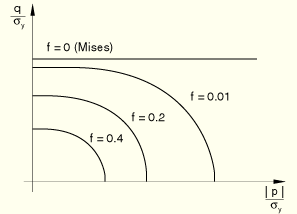
f = 0 (r = 1) implies that the material is fully dense, and the Gurson yield condition reduces to the Mises yield condition. f = 1 (r = 0) implies that the material is completely voided and has no stress carrying capacity. The model generally gives physically reasonable results only for ![]() 0.1 (
0.1 (![]() 0.9).
0.9).
The model is described in detail in “Porous metal plasticity,” Section 4.3.6 of the ABAQUS Theory Manual, along with a discussion of its numerical implementation.
If the porous metal plasticity model is used during a pore pressure analysis (see “Coupled pore fluid diffusion and stress analysis,” Section 6.7.1), the relative density, r, is tracked independently of the void ratio.
You specify the parameters ![]() ,
, ![]() , and
, and ![]() directly for the porous metal plasticity model. For typical metals the ranges of the parameters reported in the literature are
directly for the porous metal plasticity model. For typical metals the ranges of the parameters reported in the literature are ![]() = 1.0 to 1.5,
= 1.0 to 1.5, ![]() = 1.0, and
= 1.0, and ![]() =
= ![]() = 1.0 to 2.25 (see “Necking of a round tensile bar,” Section 1.1.9 of the ABAQUS Benchmarks Manual). The original Gurson model is recovered when
= 1.0 to 2.25 (see “Necking of a round tensile bar,” Section 1.1.9 of the ABAQUS Benchmarks Manual). The original Gurson model is recovered when ![]() =
= ![]() =
= ![]() = 1.0. You can define these parameters as tabular functions of temperature and/or field variables.
= 1.0. You can define these parameters as tabular functions of temperature and/or field variables.
| Input File Usage: | *POROUS METAL PLASTICITY |
| ABAQUS/CAE Usage: | Property module: material editor: Mechanical |
The porous metal plasticity model in ABAQUS/Explicit allows for failure. In this case the yield condition is written as
![]()
![]()
| Input File Usage: | Use the following option in conjunction with the *POROUS METAL PLASTICITY option: |
*POROUS FAILURE CRITERIA |
| ABAQUS/CAE Usage: | Property module: material editor: Mechanical |
You can specify the initial relative density of the porous material, ![]() , at material points or at nodes. If you do not specify the initial relative density, ABAQUS will assign it a value of 1.0.
, at material points or at nodes. If you do not specify the initial relative density, ABAQUS will assign it a value of 1.0.
You can specify the initial relative density as part of the porous metal plasticity material definition.
| Input File Usage: | *POROUS METAL PLASTICITY, RELATIVE DENSITY= |
| ABAQUS/CAE Usage: | Property module: material editor: Mechanical |
Alternatively, you can specify the initial relative density at nodes as initial conditions (“Initial conditions,” Section 27.2.1); these values are interpolated to the material points. The initial conditions are applied only if the relative density is not specified as part of the porous metal plasticity material definition. When a discontinuity of the initial relative density field occurs at the element boundaries, separate nodes must be used to define the elements at these boundaries, with multi-point constraints applied to make the nodal displacements and rotations equivalent.
| Input File Usage: | *INITIAL CONDITIONS, TYPE=RELATIVE DENSITY |
| ABAQUS/CAE Usage: | Initial relative density is not supported in ABAQUS/CAE. |
The presence of pressure in the yield condition results in nondeviatoric plastic strains. Plastic flow is assumed to be normal to the yield surface:
![]()
![]()
The model is illustrated in Figure 18.2.9–1, where the yield surfaces for different levels of void volume fraction are shown in the p–q plane.
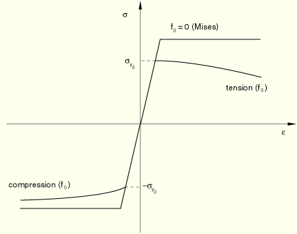
Figure 18.2.9–2 compares the behavior of a porous material (whose initial yield stress is ![]() ) in tension and compression against the behavior of the perfectly plastic matrix material. In compression the porous material “hardens” due to closing of the voids, and in tension it “softens” due to growth and nucleation of the voids.
) in tension and compression against the behavior of the perfectly plastic matrix material. In compression the porous material “hardens” due to closing of the voids, and in tension it “softens” due to growth and nucleation of the voids.
The total change in void volume fraction is given as
![]()
![]()
![]()
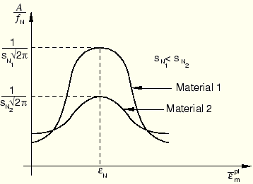
The nucleation function ![]() is assumed to have a normal distribution, as shown in Figure 18.2.9–3 for different values of the standard deviation
is assumed to have a normal distribution, as shown in Figure 18.2.9–3 for different values of the standard deviation ![]() .
.
The following ranges of values are reported in the literature for typical metals: ![]() = 0.1 to 0.3,
= 0.1 to 0.3, ![]() 0.05 to 0.1, and
0.05 to 0.1, and ![]() = 0.04 (see “Necking of a round tensile bar,” Section 1.1.9 of the ABAQUS Benchmarks Manual). You specify these parameters, which can be defined as tabular functions of temperature and predefined field variables. ABAQUS will include void nucleation in a tensile field only when you include it in the material definition.
= 0.04 (see “Necking of a round tensile bar,” Section 1.1.9 of the ABAQUS Benchmarks Manual). You specify these parameters, which can be defined as tabular functions of temperature and predefined field variables. ABAQUS will include void nucleation in a tensile field only when you include it in the material definition.
| Input File Usage: | *VOID NUCLEATION |
| ABAQUS/CAE Usage: | Property module: material editor: Mechanical |
There are cases when we need to study the behavior of a material that has already been subjected to some work hardening. For such cases ABAQUS allows you to prescribe initial conditions directly for the equivalent plastic strain, ![]() (“Initial conditions,” Section 27.2.1).
(“Initial conditions,” Section 27.2.1).
| Input File Usage: | *INITIAL CONDITIONS, TYPE=HARDENING |
| ABAQUS/CAE Usage: | Initial equivalent plastic strain is not supported in ABAQUS/CAE. |
For more complicated cases, initial conditions can be defined in ABAQUS/Standard through user subroutine HARDINI.
| Input File Usage: | *INITIAL CONDITIONS, TYPE=HARDENING, USER |
| ABAQUS/CAE Usage: | User subroutine HARDINI is not supported in ABAQUS/CAE. |
The porous metal plasticity model can be used with any stress/displacement elements other than one-dimensional elements (beam and truss elements) or elements for which the assumed stress state is plane stress (plane stress, shell, and membrane elements).
In addition to the standard output identifiers available in ABAQUS (“ABAQUS/Standard output variable identifiers,” Section 4.2.1, and “ABAQUS/Explicit output variable identifiers,” Section 4.2.2), the following variables have special meaning in the porous metal plasticity model:
PEEQ | Equivalent plastic strain, |
VVF | Void volume fraction. |
VVFG | Void volume fraction due to void growth. |
VVFN | Void volume fraction due to void nucleation. |
Gurson, A. L., “Continuum Theory of Ductile Rupture by Void Nucleation and Growth: Part I—Yield Criteria and Flow Rules for Porous Ductile Materials,” Journal of Engineering Materials and Technology, vol. 99, pp. 2–15, 1977.
Tvergaard, V., “Influence of Voids on Shear Band Instabilities under Plane Strain Condition,” International Journal of Fracture Mechanics, vol. 17, pp. 389–407, 1981.