Products: ABAQUS/Standard ABAQUS/CAE
ALE adaptive meshing in ABAQUS/Standard:
maintains a topologically similar mesh;
can be used to solve Lagrangian problems (in which no material leaves the mesh) and to model effects of ablation, or wear (in which material is eroded at the boundary);
can be used in static stress/displacement analysis, steady-state transport analysis, coupled pore fluid flow and stress analysis, and coupled temperature-displacement analysis;
can be used only in geometrically nonlinear general analysis steps; and
is available only for acoustic elements and a subset of the solid elements.
You can apply ALE adaptive mesh smoothing to an entire model or to individual parts of the model as a step-dependent feature. Adaptive meshing for solid elements in ABAQUS/Standard uses a subset of the adaptive meshing functionality available in ABAQUS/Explicit.
You must specify the portion of the original mesh that will be subject to adaptive meshing.
| Input File Usage: | *ADAPTIVE MESH, ELSET=name |
Multiple adaptive mesh domains can be defined in a step by reusing the *ADAPTIVE MESH option, but each element set must refer to a unique set of elements. |
| ABAQUS/CAE Usage: | Step module: Other |
Only one adaptive mesh domain can be defined in ABAQUS/CAE for any particular step. |
By default, all adaptive mesh domains defined in the previous analysis step remain unchanged in the subsequent step. You define the adaptive mesh domains in effect for a given step relative to the preexisting adaptive mesh domains. At each new step the existing adaptive mesh domains can be modified and additional adaptive mesh domains can be specified (except in ABAQUS/CAE, where only one adaptive mesh domain can be in effect for a given step).
| Input File Usage: | Use either of the following options to modify an existing adaptive mesh domain or to specify an additional adaptive mesh domain: |
*ADAPTIVE MESH, ELSET=name *ADAPTIVE MESH, ELSET=name, OP=MOD |
| ABAQUS/CAE Usage: | Step module: Other |
If you choose to remove any adaptive mesh domain in a step, no adaptive mesh domains will be propagated from the previous step. Therefore, all adaptive mesh domains that are in effect during this step must be respecified.
| Input File Usage: | Use the following option to remove all previously defined adaptive mesh domains and to specify new adaptive mesh domains: |
*ADAPTIVE MESH, ELSET=name, OP=NEW If the OP=NEW parameter is used on any *ADAPTIVE MESH option within a step, it must be used on all *ADAPTIVE MESH options in the step. |
| ABAQUS/CAE Usage: | Step module: Other |
ABAQUS/Standard may subdivide each adaptive mesh domain that you specify such that
all elements in an adaptive domain refer to one element property definition; and
all elements in an adaptive domain are of similar type (such as hybrid elements with linear pressure).
If ABAQUS/Standard subdivides the adaptive mesh domains that you specified, each of the adaptive mesh domain subdivisions will have a new name, which will be used for output and diagnostic purposes. The new names will be formed by concatenating the name of the user-specified element set, a number identifying the subdivision, and the step number. Each of the subdivisions will be further examined to ensure that all the elements in a subdivision are subjected to the same body forces. You may be asked to modify the definition of the adaptive mesh domain to satisfy this requirement.
Each adaptive mesh domain has an interior region and a boundary region. The boundary region may include distinct kinks that take the form of geometric edges or corners. The nodes on the boundary region are, therefore, further separated into free surface nodes, edge nodes, and constrained nodes. Different updating rules are applied to nodes in these different regions. These regions are created automatically by ABAQUS/Standard. You can control the detection of the geometric features. In addition, mesh constraints can be applied to any node in the adaptive mesh domain.
Since acoustic elements do not have displacement degrees of freedom, their treatment for adaptive meshing includes some additional considerations. The acoustic adaptive domain must be connected to the structural domain using a surface-based tie constraint with the slave surface defined on the acoustic domain. Thus, an acoustic adaptive domain has an additional boundary region that is connected to the structural domain. These slave surface nodes are updated based on the displaced configuration of the master surface nodes on the structural domain, without permitting relative sliding between the surfaces. The displacements of the master surface defined on the structural domain, together with nonzero adaptive mesh constraints, serve as the forcing function that drives adaptive mesh smoothing of an acoustic adaptive domain. The mesh smoothing algorithm will produce no changes in the acoustic adaptive domain if these displacements are zero.
Options for controlling the mesh smoothing algorithm are described in “ALE adaptive meshing and remapping in ABAQUS/Standard,” Section 12.2.7.
Nodes in the interior region are defined as nodes that are surrounded entirely by elements in the adaptive mesh domain. By default, the new position of an interior node is computed from the positions of the adjacent nodes that are connected through element edges to the node in question. These nodes can move in any direction.
To control the displacement of these nodes, you can apply an adaptive mesh constraint in any direction.
The boundary region is that part of the surface of the adaptive mesh domain that is not constrained to other elements in the mesh. The nodes on the boundary region are further separated into surface nodes, edge nodes, corner nodes, and constrained nodes.
Surface nodes are defined as nodes at which the surrounding surface facets have the same normal vector within a user-defined angle. These nodes are constrained against movement in the normal direction, but sliding in any tangential direction is permitted. The new position of a surface node is computed from the positions of the adjacent nodes that are connected through the edges of the surface facets to the node in question.
Edge nodes are nodes in a three-dimensional model at which the surrounding surface facets have two different normals and where the vectors along two of the surface edges are colinear. Nodes on an edge can slide only along the edge. The new position of an edge node is computed from the positions of the two adjacent nodes along the edge.
Corner nodes are nodes at which all the surrounding surface facet normals are different. These nodes are constrained against all mesh smoothing movement.
You can control the displacement of these node types on the boundary region by applying an adaptive mesh constraint in any direction.
A surface-based tie constraint can be used to connect two acoustic surfaces together. When both the master and slave nodes of the tie constraint belong to the same adaptive mesh domain, the master surface nodes are updated according to the rules for surface, edge, and corner nodes. An adaptive mesh constraint can be applied at master surface nodes. Slave nodes are updated by applying a tie constraint. Adaptive mesh constraints cannot be applied at slave surface nodes.
Mesh smoothing is not applied to these nodes when the master and slave nodes belong to different acoustic adaptive mesh domains.
Mesh smoothing is not applied to nodes that are involved in multi-point constraints (see “General multi-point constraints,” Section 28.2.2) or equations (see “Linear constraint equations,” Section 28.2.1).
The classification of boundary region nodes as surface, edge, and corner nodes is performed based on the identification of geometric features in the mesh's configuration at the start of a step where adaptive mesh domains are defined and is updated as the analysis proceeds and the configuration changes. You can define the criteria that ABAQUS/Standard uses in classifying geometric features through adaptive mesh controls.
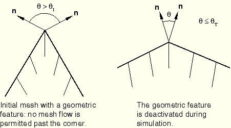
Geometric features are identified initially as edges on boundary regions where the angle between the normals on adjacent element faces is greater than the initial geometric feature angle, ![]() (
(![]() ), as shown in Figure 12.2.6–1. The default value for the initial geometric feature angle is
), as shown in Figure 12.2.6–1. The default value for the initial geometric feature angle is ![]() . Setting
. Setting ![]() will ensure that no geometric edges or corners are formed on the boundary of the adaptive mesh domain. You can define adaptive mesh controls to change the value of the angle that will be used to recognize geometric features.
will ensure that no geometric edges or corners are formed on the boundary of the adaptive mesh domain. You can define adaptive mesh controls to change the value of the angle that will be used to recognize geometric features.
| Input File Usage: | *ADAPTIVE MESH CONTROLS, NAME=name, INITIAL FEATURE ANGLE= |
| ABAQUS/CAE Usage: | Step module: Other |
ABAQUS/Standard allows geometric features, and consequently the updating rules applied at a node, to change during the analysis. For example, nodes are constrained to lie along a discrete geometric edge unless the angle forming the geometric edge becomes less than the transition geometric feature angle, ![]() (
(![]() ). The default value for the transition feature angle is
). The default value for the transition feature angle is ![]() . If the angle across the geometric edge becomes less than
. If the angle across the geometric edge becomes less than ![]() , the boundary surface is considered to be flattened sufficiently for the feature to be deactivated, and the mesh is allowed to slide freely on the surface. Geometric corners are allowed to flatten in a similar fashion. In addition, surfaces that are initially flat may develop edges or corners during the simulation. This logic allows great flexibility in mesh adaptation while preserving geometric features in the model.
, the boundary surface is considered to be flattened sufficiently for the feature to be deactivated, and the mesh is allowed to slide freely on the surface. Geometric corners are allowed to flatten in a similar fashion. In addition, surfaces that are initially flat may develop edges or corners during the simulation. This logic allows great flexibility in mesh adaptation while preserving geometric features in the model.
Setting ![]() will ensure that no geometric edges or corners are ever deactivated. You can change the transition feature angle using adaptive mesh controls.
will ensure that no geometric edges or corners are ever deactivated. You can change the transition feature angle using adaptive mesh controls.
ABAQUS/Standard will issue a warning message when geometric features are activated or deactivated.
| Input File Usage: | *ADAPTIVE MESH CONTROLS, NAME=name, TRANSITION FEATURE ANGLE= |
| ABAQUS/CAE Usage: | Step module: Other |
In most adaptive mesh problems the motion of nodes in the mesh is determined by the mesh smoothing algorithm, with constraints imposed by the domain boundary and the boundary region edges. However, there may be cases when you will want to define the motion of the nodes explicitly. You may also wish to keep certain nodes fixed, to move nodes in a particular direction, or to force certain nodes to move with the material.
Adaptive mesh constraints give you the flexibility to define the motion of the node explicitly.
| Input File Usage: | *ADAPTIVE MESH CONSTRAINT |
| ABAQUS/CAE Usage: | Step module: Other |
Spatial mesh constraints are applied to define the motion of the nodes explicitly. Spatial mesh constraints allow full control over the mesh movement and can be applied to any node except those that have Lagrangian mesh constraints applied to them.
You can also prescribe the spatial mesh constraints via user subroutine UMESHMOTION. The user subroutine allows you to let the spatial mesh constraints depend on available nodal or material point information.
| Input File Usage: | Use the following option to define the mesh constraints explicitly: |
*ADAPTIVE MESH CONSTRAINT, CONSTRAINT TYPE=SPATIAL,
TYPE=DISPLACEMENT or VELOCITY
Use the following option to define the mesh constraints in user subroutine UMESHMOTION: *ADAPTIVE MESH CONSTRAINT, CONSTRAINT TYPE=SPATIAL, TYPE=DISPLACEMENT or VELOCITY, USER |
| ABAQUS/CAE Usage: | To define the mesh constraints explicitly: |
Step module: Other To define the mesh motion in user subroutine UMESHMOTION: Step module: Other |
The prescribed magnitude of a nonzero mesh constraint can vary with time during a step according to an amplitude definition (see “Amplitude curves,” Section 27.1.2).
| Input File Usage: | Use both of the following options: |
*AMPLITUDE, NAME=name *ADAPTIVE MESH CONSTRAINT, AMPLITUDE=name |
| ABAQUS/CAE Usage: | Step module: Other |
Mesh constraints are applied in local directions if a transformed coordinate system is used at a node (“Transformed coordinate systems,” Section 2.1.5); otherwise, they are applied in global directions.
Lagrangian mesh constraints on a node are used to indicate that mesh smoothing should not be applied; i.e., the node must follow the material.
| Input File Usage: | *ADAPTIVE MESH CONSTRAINT, CONSTRAINT TYPE=LAGRANGIAN |
| ABAQUS/CAE Usage: | Step module: Other |
ABAQUS/Standard will apply the user-specified spatial mesh constraint without regard to the current material displacement at the node. This behavior allows you to provide a mesh displacement that differs from the current material displacement at the free surface of the adaptive mesh domain, effectively eroding, or adding, material at the boundary. Using adaptive mesh constraints this way is an effective technique for modeling wear or ablation processes. For general boundary shapes the most effective interface for ablation is user subroutine UMESHMOTION, where you can apply spatial mesh constraints to the nodes on the free surface in general ways according to solution-dependent variables, if needed. The user subroutine interface provides a local coordinate system that is normal to the free surface at the surface node, enabling you to describe mesh motions in this local system.
By default, all adaptive mesh constraints defined in the previous analysis step remain unchanged in the subsequent step. You define the adaptive mesh constraints in effect for a given step relative to the preexisting adaptive mesh constraints. At each new step the existing adaptive mesh constraints can be modified and additional adaptive mesh constraints can be specified.
| Input File Usage: | Use either of the following options to modify an existing adaptive mesh constraint or to specify an additional adaptive mesh constraint: |
*ADAPTIVE MESH CONSTRAINT, *ADAPTIVE MESH CONSTRAINT, OP=MOD |
| ABAQUS/CAE Usage: | Step module: Other |
If you choose to remove any adaptive mesh constraint in a step, no adaptive mesh constraints will be propagated from the previous step. Therefore, all adaptive mesh constraints that are in effect during this step must be respecified.
| Input File Usage: | Use the following option to remove all previously defined adaptive mesh constraints and to specify new adaptive mesh constraints: |
*ADAPTIVE MESH CONSTRAINT, OP=NEW If the OP=NEW parameter is used on any *ADAPTIVE MESH CONSTRAINT option within a step, it must be used on all *ADAPTIVE MESH CONSTRAINT options in the step. |
| ABAQUS/CAE Usage: | Step module: Other |
When surfaces are defined for large-sliding contact, adaptive meshing may relocate the nodes on the surfaces. If the bodies in contact are sliding or deforming considerably, you may want to use Lagrangian mesh constraints on the boundary of the surfaces to prevent the surfaces from sliding from their intended place.
For small-sliding contact ABAQUS/Standard assumes that the reference configuration does not change significantly. If the reference configuration does not change significantly, the amount of adaptive meshing on these surfaces should be small and the contact quantities computed based on the reference configuration should continue to remain valid (ABAQUS/Standard updates the tangent planes if nodes change positions). Hence, ABAQUS/Standard will allow the nodes on the contact surface to move as needed by the mesh smoothing. You should apply Lagrangian mesh constraints in cases where nodes are intended to remain nonadaptive.
Initial temperatures and field variables can be defined on any region subjected to adaptive mesh smoothing. However, these variables will not be remapped from the original to the updated configuration.
For elements with displacement degrees of freedom, no restrictions are made to loads applied to adaptive mesh domains. In cases where loads are intended to follow the material motion, Lagrangian mesh constraints must be applied to the nodes on the boundary of the surface on which distributed loads are applied to prevent the surface from sliding. This will allow adaptive meshing to occur inside the surface while maintaining the location of the distributed load.
All the nodes on which concentrated loads are applied become nonadaptive.
The loads that can be applied to an acoustic domain are described in “Acoustic, shock, and coupled acoustic-structural analysis,” Section 6.9.1. These loads cannot be applied in procedures in which mesh smoothing can be performed.
Special consideration is given to nodes on which boundary conditions are applied. No adaptive meshing is done in the direction in which the boundary condition is applied, but adaptive meshing is carried out in other directions. When a boundary condition is removed (see “Boundary conditions,” Section 27.3.1) in a step, the same restriction applies since ABAQUS/Standard will ramp off the contribution of the boundary condition over the duration of the step.
The boundary conditions that can be applied to an acoustic domain are described in “Acoustic, shock, and coupled acoustic-structural analysis,” Section 6.9.1. These boundary conditions cannot be applied in any analysis procedure in which mesh smoothing can be performed.
There are no restrictions on applying prescribed temperatures or field variables in an adaptive mesh domain, but these nodal values are not remapped when adaptive meshing is performed. Therefore, predefined fields that are not constant may not be meaningful in an adaptive mesh domain.
For elements with displacement degrees of freedom all material models that are isotropic and homogeneous can be used in an adaptive domain. Material options that have anisotropic behavior such as anisotropic materials (see “Defining fully anisotropic elasticity” in “Linear elastic behavior,” Section 17.2.1), jointed material models (see “Jointed material model,” Section 18.4.1), and concrete material models (see “Concrete smeared cracking,” Section 18.5.1) cannot be used in an adaptive mesh domain.
For acoustic elements the relevant material models are described in “Acoustic, shock, and coupled acoustic-structural analysis,” Section 6.9.1. Mesh smoothing assumes that the geometric changes in the acoustic domain do not lead to changes in material properties, such as fluid density.
Adaptive mesh domains can be defined for all acoustic first-order and second-order planar, axisymmetric, and three-dimensional elements in ABAQUS/Standard and for a limited number of other elements. Table 12.2.6–1 provides a list of supported elements.
Table 12.2.6–1 Elements supported for adaptive meshing.
| AC1D2, AC1D3, AC2D3, AC2D4, AC2D6, AC2D8, AC3D4, AC3D6, AC3D8, AC3D10, AC3D15, AC3D20, ACAX3, ACAX4, ACAX6, ACAX8 |
| CPS4, CPS4T, CPS3 |
| CPE4, CPE4H, CPE4T, CPE4HT, CPE4P, CPE4PH, CPE3, CPE3H |
| CAX4, CAX4H, CAX4T, CAX4HT, CAX4P, CAX4PH, CAX3, CAX3H |
| C3D8, C3D8R, C3D8H, C3D8RH, C3D8T, C3D8HT, C3D8RT, C3D8RHT, C3D8P, C3D8PH, C3D8RP, C3D8RPH |
Adaptive meshing can be used only in geometrically nonlinear general steps that invoke one of the following procedures:
Static stress/displacement analysis (“Static stress analysis procedures: overview,” Section 6.2.1)
Steady-state transport analysis (“Steady-state transport analysis,” Section 6.4.1)
Coupled temperature-displacement analysis (“Fully coupled thermal-stress analysis,” Section 6.5.4)
Coupled pore fluid flow and stress analysis (“Coupled pore fluid diffusion and stress analysis,” Section 6.7.1)
Acoustic elements will typically undergo adaptive meshing during static procedures and then participate in subsequent acoustic procedures in their updated configuration.
Elements within the adaptive domain cannot be removed or added (“Element and contact pair removal and reactivation,” Section 11.2.1).
Deformable elements that are declared rigid cannot be part of adaptive mesh domains.
Elements in the adaptive domain cannot contain embedded elements or rebars.
Symmetric results transfer cannot be done from an axisymmetric model that had solid elements in an adaptive domain.
Import cannot be done from a model that had solid elements in the adaptive domain.
It is not meaningful to drive a submodel using the nodes from a global model that were part of an adaptive mesh domain.
Only enhanced hourglass control can be used with reduced-integration elements.
When used with acoustic elements, adaptive mesh smoothing must be applied in steps prior to a coupled structural-acoustic analysis. It cannot be applied during a large-displacement dynamic analysis.
Mesh smoothing assumes that the geometric changes in the acoustic domain do not lead to changes in material properties, such as fluid density.
The coupling between the fluid and structure must be defined using a surface-based tie constraint with the slave surface defined on the acoustic domain.
*HEADING
…
*ELEMENT, TYPE=…, ELSET=ACOUSTIC
Data lines to define acoustic elements
*ELEMENT, TYPE=…, ELSET=SOLID
Data lines to define structural elements
*SURFACE, NAME=TIE_ACOUSTIC
Data lines to define the acoustic surface interface with the structural mesh
*SURFACE, NAME=TIE_SOLID
Data lines to define the solid surface interface with the acoustic mesh
*TIE, NAME=COUPLING
TIE_ACOUSTIC, TIE_SOLID
…
*STEP
*STATIC
*ADAPTIVE MESH, ELSET=ACOUSTIC, MESH SWEEP=10
…
*END STEP
**
*STEP
*STEADY STATE DYNAMICS, DIRECT
…
*END STEP
*HEADING
…
*ELEMENT, TYPE=C3D8, ELSET=..
Data lines to define solid elements
*NSET, NSET=LAG
Data lines to define nodes that should be nonadaptive
*NSET, NSET=SPATIAL
Data lines to define nodes that will have spatial adaptive mesh constraints applied
*ELEMENT, TYPE=…, ELSET=SOLID
Data lines to define structural elements
*STEP, NLGEOM=YES
*STATIC
*ADAPTIVE MESH, ELSET=SOLID, MESH SWEEP=10
*ADAPTIVE MESH CONSTRAINT, CONSTRAINT TYPE=LAGRANGIAN
LAG
*ADAPTIVE MESH CONSTRAINT, CONSTRAINT TYPE=SPATIAL, USER
SPATIAL
*END STEP