Your next task is to create instances of your parts. A part instance can be thought of as a representation of the original part; an instance is not a copy of a part. You can then position these part instances in a global coordinate system to create the assembly.
An instance maintains its association with the original part. If the geometry of a part changes, ABAQUS/CAE automatically updates all instances of the part to reflect these changes. You cannot edit the geometry of a part instance directly. The assembly can contain multiple instances of a single part; for example, a rivet that is used repeatedly in a sheet metal assembly.
An instance may be independent or dependent. Independent part instances are meshed individually, while the mesh of a dependent part instance is associated with the mesh of the original part. Part meshing is discussed further in “Meshing the assembly,” Section C.11. By default, part instances are dependent.
When you create a part instance, ABAQUS/CAE positions it so that the origin of the sketch that defined the base feature overlays the origin of the assembly's global coordinate system. In addition, the sketch plane is aligned with the X–Y plane of the global coordinate system.
When you create the first part instance, the Assembly module displays a graphic indicating the origin and the orientation of the global coordinate system. You can use this graphic to help you decide how to position a selected instance relative to the global coordinate system. For the tutorial you will keep the hinge with the lubrication hole fixed and move the second hinge and the pin relative to it.
First, you need to create the following instances:
An instance of the hinge piece with the lubrication hole—Hinge-hole.
An instance of the hinge piece with the lubrication hole removed—Hinge-solid.
An instance of the pin—Pin.
To create an instance of the hinge piece with the lubrication hole:
In the Model Tree, expand the Assembly container. Then double-click Instances in the list that appears to create a new part instance.
The Create Instance dialog box appears containing a list of all the parts in the current model—the two hinge pieces and the pin in this example.
In the dialog box, select Hinge-hole.
ABAQUS/CAE displays a temporary image of the selected part.
In the dialog box, click Apply.
ABAQUS/CAE creates a dependent instance of the hinge piece and displays a graphic indicating the origin and orientation of the global coordinate system. ABAQUS/CAE names the instance Hinge-hole-1 to indicate that it is the first instance of a part called Hinge-hole.
Note: The default position of a part instance is such that the origin and the X- and Y-axes of the sketch of the base feature align with the origin and the X- and Y-axes of the global coordinate system. For example, the base feature of the hinge piece is the original cube you created. ABAQUS/CAE positions instances of the hinge piece so that the origin of the cube sketch is located at the origin of the global coordinate system and the X- and Y-axes align.
You will now create an instance of the solid hinge piece. To separate the solid hinge piece from the instance of the hinge piece with the lubrication hole, you ask ABAQUS/CAE to offset the new instance along the X-axis.
To create an instance of the solid hinge piece:
From the Create Instance dialog box, toggle on Auto-offset from other instances.
The auto-offset function prevents new part instances from overlapping existing instances.
From the Create Instance dialog box, select Hinge-solid and click OK.
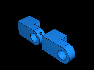
ABAQUS/CAE closes the dialog box, creates the new dependent instance, and applies an offset along the X-axis that separates the two hinges, as shown in Figure C–23. (For clarity the datum geometry has been removed from the shaded view in Figure C–23 and subsequent figures by selecting View![]() Assembly Display Options
Assembly Display Options![]() Datum.)
Datum.)
In addition to the simple translate and rotate procedures, the Assembly module provides a set of tools that allow you to position a selected part instance by defining the relationship between selected faces or edges. You can select a face (or an edge) of the instance to move, called the movable part instance, and a face (or an edge) of the instance that remains fixed, called the fixed part instance, and choose one of the following position constraints:
Parallel Face
The movable instance moves until the two selected faces are parallel.
Face to Face
The movable instance moves until the two selected faces are parallel and a specified clearance from each other.
Parallel Edge
The movable instance moves until the two selected edges are parallel.
Edge to Edge
The movable instance moves until the two selected edges are colinear or a specified distance from each other.
Coaxial
The movable instance moves until the two selected faces are coaxial.
Coincident Point
The movable instance moves until the two selected points are coincident.
Parallel CSYS
The movable instance moves until the two selected datum coordinate systems are parallel.
In this example you will move the solid hinge piece while the hinge piece with the lubrication hole will remain fixed. You will apply three types of position constraints to position the two hinge pieces correctly.
To position the solid hinge piece:
First, constrain the solid hinge piece so that the two flanges face each other. From the main menu bar, select Constraint![]() Face to Face.
Face to Face.
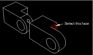
From the movable part instance, select the face of the solid hinge piece shown in Figure C–24.
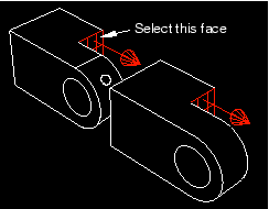
From the fixed part instance, select the face of the hinge piece with the lubrication hole shown in Figure C–25. ABAQUS/CAE highlights the face on the movable part instance in red and the face on the fixed part instance in magenta.
ABAQUS/CAE displays red arrows on each selected face; the movable instance will be positioned so that the arrows point in the same direction. You can change the direction of the arrow on the movable instance if necessary.
From the prompt area, click Flip to change the direction of the arrow. Click OK when the arrows point toward each other.
In the text box that appears in the prompt area, type the clearance (0.04) that will remain between the two parts, as measured along the normal to the selected face of the fixed part, and press [Enter].
ABAQUS/CAE rotates the solid hinge piece so that the two selected faces are parallel to each other and 0.04 meters apart, as shown in Figure C–26.
The two pieces overlap because the position of the solid hinge piece is not fully determined by the position constraint you have applied. You will need to apply two more position constraints to obtain the desired position.Next, align the two flange holes. From the main menu bar, select Constraint![]() Coaxial.
Coaxial.
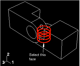
Select the flange hole on the solid hinge piece, as shown in Figure C–27. (You may find it helpful to display the wireframe view of the two pieces.)
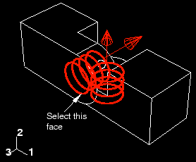
Select the flange hole on the hinge piece with the lubrication hole, as shown in Figure C–28.
ABAQUS/CAE displays red arrows on each selected face.
From the prompt area, click Flip to change the direction of the arrow on the movable part instance. Click OK when the arrow points downward.
ABAQUS/CAE positions the two hinge pieces so that the two flange holes are coaxial.
Use the rotate tool ![]() to look at the top view of the two pieces. Notice that the two flanges are now overlapping, as shown in Figure C–29.
to look at the top view of the two pieces. Notice that the two flanges are now overlapping, as shown in Figure C–29.
Finally, add a constraint to eliminate the overlap between the two flanges. From the main menu bar, select Constraint![]() Edge to Edge.
Edge to Edge.
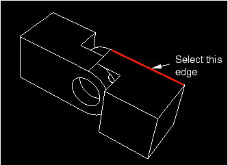
Select the straight edge on the solid hinge piece shown in Figure C–30.
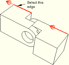
Select the corresponding edge of the hinge piece with the lubrication hole, as shown in Figure C–31.
ABAQUS/CAE displays red arrows on each selected face.
If necessary, flip the arrows so they point in the same direction; then click OK to apply the constraint.
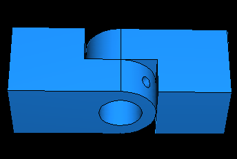
ABAQUS/CAE positions the two hinge pieces so that the two selected edges are colinear, as shown in Figure C–32.
You will now create an instance of the pin and position it symmetrically in the flange holes using constraints and translation vectors. To define the translation vector, you can select vertices from the assembly or you can enter the coordinates. You can determine the translation vector using the Query tool.
To position the pin:
In the Model Tree, double-click Instances underneath the Assembly container.
In the Create Instance dialog box, toggle off Auto-offset from other instances and create an instance of the pin.
Constrain the pin to lie along the same axis as the two flange holes. Use the Constraint![]() Coaxial menu as you did when you aligned the two flange holes in the previous section. (You can select either of the flange holes as the cylindrical surface of the fixed instance, and the direction of the arrows is not important.)
Coaxial menu as you did when you aligned the two flange holes in the previous section. (You can select either of the flange holes as the cylindrical surface of the fixed instance, and the direction of the arrows is not important.)
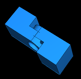
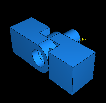
ABAQUS/CAE will position the pin as shown in Figure C–33.
From the main menu bar, select Tools![]() Query.
Query.
The Query dialog box appears.
Select Distance from the list of General Queries, and click OK.
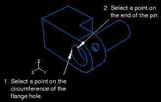
The Distance query allows you measure the X-, Y-, and Z-components of the vector connecting two selected points. You need to determine the distance between the end of the pin and the hinge containing the lubrication hole; the two points to select are illustrated in Figure C–34.
To define one end of the vector, select a point on the circumference of the hole in the flange containing the lubrication hole.
To define the other end of the vector, select the vertex on the pin that is inside the hinge containing the lubrication hole.
ABAQUS/CAE displays the vector distance between the two selected points along with the X-, Y-, and Z-components of the vector in the message area. You will translate the pin along the Z-axis; the Z-component of the distance is 0.01 meters. You want to position the pin symmetrically between the hinges, so you will translate it 0.02 meters.
From the main menu bar, select Instance![]() Translate.
Translate.
Select the pin as the part instance to move, and click Done to indicate that you have finished selecting instances to move.
In the text boxes in the prompt area, enter a start point for the translation vector of 0,0,0 and an end point of 0,0,0.02.
ABAQUS/CAE translates the pin a distance of 0.02 along the Z-axis and displays a temporary image of the new position of the pin.
Note:
If the position of a temporary image (colored red) is not correct, you can use the buttons in the prompt area to correct the problem. Click either the Cancel button (![]() ) to cancel the procedure or the Previous button (
) to cancel the procedure or the Previous button (![]() ) to step back through the procedure.
) to step back through the procedure.
From the prompt area, click OK.
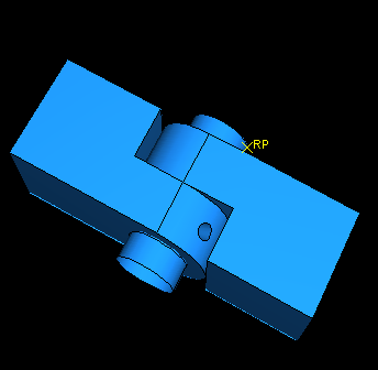
The finished assembly is shown in Figure C–35.
Before proceeding, convert all position constraints to absolute positions. From the main menu bar, select Instance![]() Convert Constraints. Select all part instances, and click Done in the prompt area.
Convert Constraints. Select all part instances, and click Done in the prompt area.