The final assembly consists of instances of the two hinge pieces that are free to rotate about a pin. You will model the pin as a three-dimensional, revolved analytical rigid surface. First you create the pin and assign the rigid body reference point; then you constrain the pin by applying constraints to this rigid body reference point.
You will now create the pin—a three-dimensional, revolved analytical rigid surface.
To create the pin:
In the Model Tree, double-click the Parts container to create a new part.
The Create Part dialog box appears.
Name the part Pin. Choose a three-dimensional body as before, but change the type to Analytical rigid and the base feature shape to Revolved shell.
Accept the approximate size of 0.2, and click Continue.
The Sketcher starts and displays the axis of revolution as a green dashed line with a fixed position constraint; your sketch cannot cross this axis.
From the Sketcher toolbox, select the connected lines tool ![]() . Sketch a vertical line to the right of the axis.
. Sketch a vertical line to the right of the axis.
Dimension the horizontal distance from the line to the axis, and change the distance to 0.012.
Dimension the vertical length of the line, and change the length to 0.06.
Click mouse button 2 to exit the Sketcher.
The sketch and the resulting shaded part are shown in Figure C–21.
You need to assign a rigid body reference point to the pin. Because you will not assign mass or rotary inertia to the pin, the rigid body reference point can be placed anywhere in the viewport. You use the Load module to apply constraints to the reference point or to define its motion. Motion or constraints that you apply to the rigid body reference point are applied to the entire rigid surface.
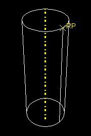
You can either select the reference point from the part in the viewport, or you can enter its coordinates. For the tutorial you will select the reference point from the viewport, as shown in Figure C–22.
To assign the reference point:
From the main menu bar, select Tools![]() Reference Point.
Reference Point.
Select one of the vertices on the circumference of the pin.
ABAQUS/CAE labels the vertex RP to indicate that the reference point has been assigned to it.