Before you apply loads or boundary conditions to the model or define contact within the model, you must define the different steps in the analysis. Once the steps are created, you can specify in which steps loads, boundary conditions, and interactions should be applied.
When you create a step, ABAQUS/CAE selects a default set of output variables corresponding to the analysis procedure and selects a default rate at which the variables are written to the output database. In this tutorial you will edit the default output frequency for the first step and edit the list of default output variables for the second step.
The analysis that you perform on the hinge model will consist of an initial step and two general analysis steps:
In the initial step you apply boundary conditions to regions of the model and define contact between regions of the model.
In the first general analysis step you allow contact to become established.
In the second general analysis step you modify two of the boundary conditions applied to the model and apply a pressure load to one of the hinge pieces.
To create the analysis steps:
In the Model Tree, double-click the Steps container to create a new step.
The Create Step dialog box appears.
In the Create Step dialog box:
Name the step Contact.
Accept the default procedure type (Static, General), and click Continue.
The step editor appears.
In the Description field, type Establish contact.
Click the Incrementation tab, and delete the value of 1 that appears in the Initial text field. Type a value of 0.1 for the initial increment size.
Click OK to create the step and to exit the editor.
The Contact step appears underneath the Steps container in the Model Tree.
Use the same technique to create a second general, static step named Load. Enter Apply load in the description field and an initial increment size of 0.1.
The Load step appears underneath the Steps container in the Model Tree.
You use field output requests to request output of variables that should be written at relatively low frequencies to the output database from the entire model or from a large portion of the model. Field output is used to generate deformed shape plots, contour plots, and animations from your analysis results. ABAQUS/CAE writes every component of the variables to the output database at the selected frequency.
You use history output requests to request output of variables that should be written to the output database at a high frequency from a small portion of the model; for example, the displacement of a single node. History output is used to generate X–Y plots and data reports from your analysis results. When you create a history output request, you must select the individual components of the variables that will be written to the output database.
The default field output variables for the Contact and Load steps include the following:
S (Stress components)
PE (Plastic strain components)
PEEQ (Equivalent plastic strain)
PEMAG (Plastic strain magnitude)
LE (Logarithmic strain components)
U (Translations and rotations)
RF (Reaction forces and moments)
CF (Concentrated forces and moments)
CSTRESS (Contact stresses)
CDISP (Contact displacements)
To edit an output request and to specify the output frequency during the Load step:
In the Model Tree, click mouse button 3 on the Field Output Requests container and select Manager from the menu that appears.
The Field Output Requests Manager appears. The Field Output Requests Manager is a step-dependent manager. The types of objects that appear in step-dependent managers are those that you can create, modify, and deactivate in particular analysis steps. Step-dependent managers display information concerning the history of each object listed in the manager. In this example ABAQUS/CAE named the default field output request that you created in the Contact step F-Output-1. In addition ABAQUS/CAE propagated the output request into the Load step. For more information, see “Managing objects,” Section 3.4 of the ABAQUS/CAE User's Manual.
From the Field Output Requests Manager, select the F-Output-1 output request in the Contact step and click Edit.
The Edit Field Output Request editor appears for the Contact step.
Select Last increment as the output frequency to generate output only during the last increment of the step.
Click OK to modify the output request.
From the Field Output Requests Manager, select the F-Output-1 output request in the Load step. From the buttons on the right side of the manager, click Edit.
The Edit Field Output Request editor appears for the Load step.
Set the output frequency to 1 to generate output during every increment of the step.
From the list of output categories, click the arrow to the left of Contact.
A list of the contact output variables available appears along with a description of each.
Click the check box next to CDISP to deselect this variable for output.
The check box next to Contact remains light gray with a dark gray check mark to indicate that not all variables in this category will be output. The Edit Field Output Request editor also indicates the following:
Output will be generated for the whole model.
Output will be generated at default section points.
Output will include local coordinate transformations (when available).
Click OK to modify the output request.
In the Field Output Requests Manager the status of the output request changes to Modified for the Load step.
At the bottom of the Field Output Requests Manager, click Dismiss to close the dialog box.
You can define particular element or node sets that contain only selected portions of your model. Once you create a set, you can use it to perform the following tasks:
Assign section properties in the Property module.
Create contact pairs with contact node sets and surfaces in the Interaction module.
Define loads and boundary conditions in the Load module.
Request output to either the output database or the status file from specific regions of the model in the Step module. Output to the status file is also reported back to the Job module in the form of a continuously updated X–Y plot.
Display results for specific regions of the model in the Visualization module.
To create a set and monitor a particular degree of freedom:
In the Model Tree, expand the Assembly container and double-click the Sets item.
The Create Set dialog box appears.
Name the set Monitor, and click Continue.
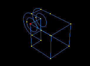
Select the vertex of the solid hinge piece shown in Figure C–36.
Click Done to indicate that you have finished selecting the geometry for the set.
ABAQUS/CAE creates a node set with the name Monitor that contains the node you selected.
From the main menu bar of the Step module, select Output![]() DOF Monitor.
DOF Monitor.
The DOF Monitor dialog box appears.
Toggle on Monitor a degree of freedom throughout the analysis.
Click Edit, then click Points in the prompt area and choose the node set Monitor from the Region Selection dialog box.
Type 1 in the Degree of freedom text field, and click OK.