Product: ABAQUS/Explicit
This example illustrates the use of the general contact capability in a simulation involving a large number of contacting bodies. The general contact algorithm, specified using the *CONTACT option, allows very simple definitions of contact with very few restrictions on the types of surfaces involved (see “Defining general contact interactions,” Section 29.3.1 of the ABAQUS Analysis User's Manual).
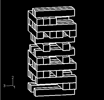
The model simulates the collapse of a stack of blocks. The undeformed configuration of the model is shown in Figure 2.1.11–1. There are 35 blocks, and each block is 12.7 × 12.7 × 76.2 mm (0.5 × 0.5 × 3 inches) in size. The blocks are stacked on a rigid floor. The stack is subjected to gravity loading. It is assumed that a key block near the bottom of the stack has been removed just before the start of the analysis, initiating the collapse.
Each block is modeled with a single C3D8R element. The use of a coarse mesh highlights the edge-to-edge contact capability of the general contact algorithm, because the majority of the block-to-block interactions do not result in penetrations of nodes into faces.
Two different cases are analyzed. In the first analysis the blocks are rigid. In the second analysis the blocks are deformable. In the latter case, the material of the block is assumed to be linear elastic with a Young's modulus of 12.135 GPa (1.76 × 10⁶ Psi), a Poisson's ratio of 0.3, and a density of 577.098 kg/m3 (5.4 × 10⁻⁵ lb s2/in4). Only the density is relevant for the analysis assuming rigid blocks. In addition, ENHANCED hourglass control is used for the deformable analysis. The rigid floor is modeled as a discrete rigid surface using a single R3D4 element.
This model involves a large number of contacting bodies. The general contact capability greatly simplifies the contact definition, since each of the 595 possible block-to-block pairings does not need to be specified individually. The general contact domain is defined with the ALL ELEMENT BASED parameter on the *CONTACT INCLUSIONS option. This parameter specifies contact automatically for the entire model and is the simplest way to define the contact domain. Coulomb friction with a friction coefficient of 0.15 is assumed between the individual blocks and between the blocks and floor. The *CONTACT PROPERTY ASSIGNMENT option is used to assign this nondefault contact property.
By default, the general contact algorithm in ABAQUS/Explicit accounts for edge-to-edge contact of perimeter edges on structural elements. Geometric feature edges of a model can also be considered for edge-to-edge contact by the general contact algorithm; including the geometric feature edges is crucial in this analysis. A cutoff feature angle of 20° is specified on the data line for the *SURFACE PROPERTY ASSIGNMENT, PROPERTY=FEATURE EDGE CRITERIA option to indicate that all edges with feature angles greater than 20° should be considered for edge-to-edge contact. The feature angle is the angle formed between the normals of the two facets connected to an edge.
The magnitude of the gravity loading is increased by a factor of 10 to facilitate demonstration of the edge-to-edge contact capability with a short analysis time. The analysis is performed for a period of 0.15 seconds. For the analysis with rigid blocks there is no deformable element available in the model to control the stable time increment. A fixed time increment of 1 × 10⁻⁶ seconds is specified for this purpose, which is similar to the time increment used by the analysis with deformable blocks. The time increment chosen for the analysis with rigid blocks will affect the penalty stiffness used by the contact algorithm since the penalty stiffness is inversely proportional to the time increment squared.
Results are shown for the rigid body case. Results for the deformable case are very similar to the rigid model results.
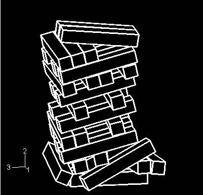
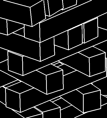
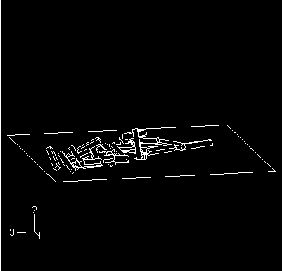
Figure 2.1.11–2 shows the displaced shape of the block assembly after 0.0375 seconds. The stack of blocks has started to collapse under gravity loading. Figure 2.1.11–3 shows a close-up view of the collapsing blocks after 0.1125 seconds. This figure clearly shows that the geometric feature edges of individual blocks contact each other during collapse. Figure 2.1.11–4 shows the final configuration of the blocks. The stack has collapsed completely on the rigid surface.
Input file for the rigid body analysis.
External file referenced by the rigid body analysis.
Input file for the deformable analysis.
External file referenced by the deformable analysis.