Product: ABAQUS/Explicit
This example illustrates the use of the general contact capability in a simulation involving a large number of contacting surfaces. The general contact algorithm, specified using the *CONTACT option, allows very simple definitions of contact with very few restrictions on the types of surfaces involved (see “Defining general contact interactions,” Section 29.3.1 of the ABAQUS Analysis User's Manual).
This model simulates crimp forming. Modern automobiles contain several thousand crimp joints. In a crimp joint a multi-strand wire bundle is mechanically joined to an end terminal to provide electrical continuity across the joint. The portion of the terminal that is folded over and into the wire bundle during crimping is called the grip. Proper design of a crimp joint depends on a number of competing factors including the diameter and number of the wire strands; the thickness, length, and material of the grip; and the geometry and surface finish of the crimp tooling. Out-of-plane extrusion of the wire bundle and grip during crimping is a significant factor in crimp formation.
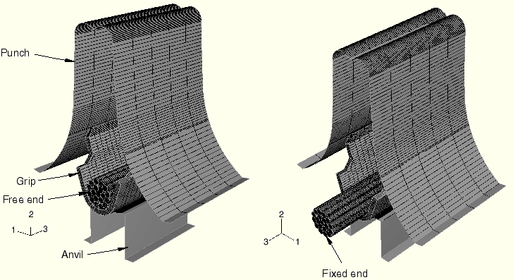
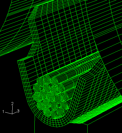
In this example the grip is 0.25 mm thick and has a 50% coin at the tips. Coining is done to help the grip arms curl over the wire bundle as they are pushed against the roof of the punch during crimping. The grip arm tips are 3.28 mm apart initially (wing tip width). A nineteen-strand wire bundle is used, with each strand having a 0.28 mm diameter. Figure 2.1.10–1 shows the model geometry prior to crimp forming. Figure 2.1.10–2 shows a close-up view of the wire-grip assembly.
The deformable wires and the grip are modeled with C3D8R elements. The punch and the anvil are modeled as rigid parts using R3D4 elements. The grip is made of a half hard copper alloy that is modeled as a von Mises elastic strain hardening plastic material with a Young's modulus of 112 GPa, a Poisson's ratio of 0.34, and a yield stress of 391 MPa. The wires are made of copper that is modeled as a strain hardening plastic material with a Young's modulus of 117 GPa, a Poisson's ratio of 0.35, and a yield stress of 241.5 MPa.
An explicit dynamic simulation is used because the following aspects would present difficulties for a static analysis with ABAQUS/Standard:
The model has no static stability due to the free rigid body motion of the grip and wires.
During crimping the grip arms buckle as they are turned by the punch downward into the bundle.
There is complex multi-body contact in the analysis: between the grip arms and the nineteen wires, between each combination of two wires, and between the two grip arms.
The rigid punch has to undergo a downward stroke of 6.88 mm to complete the crimp forming. The punch is moved downward at varying speeds to conduct the analysis efficiently without having inertia effects significantly influence the solution. Initially the punch is moved at an average speed of 50 mm/sec to establish contact between the grip arms and the rigid punch. Then the punch is moved at 300 mm/sec until the tip of the grip arms reach the roof of the punch. In the final phase the punch is slowed to about 20 mm/sec while the grip arms buckle and fold over into the wire bundle. The overall analysis time is about 0.12 seconds.
The general contact algorithm in ABAQUS/Explicit is used for this analysis. The contact domain is defined simply by specifying the ALL ELEMENT BASED parameter on the *CONTACT INCLUSIONS option. This parameter specifies self-contact for an unnamed, all-inclusive, element-based surface (defined automatically by ABAQUS/Explicit) that contains all exterior element faces in the model, as well as the nodes attached to these faces. Since this surface spans all the bodies in the model, self-contact for this surface includes interactions between all of the bodies. The contact pair algorithm cannot use surfaces that span multiple bodies; thus, using the contact pair approach for this model would be very tedious. Since there are 22 contacting parts in the model, 231 contact pairs would need to be defined to account for all the possible two-surface combinations, in addition to one contact pair needed to model self-contact for the grip.
Geometric feature edges of a model can also be considered for edge-to-edge contact by the general contact algorithm if a cutoff feature angle is specified. The feature angle is the angle formed between the normals of the two facets connected to an edge. Most of the interactions in this analysis can be detected by node-to-facet contact and, thus, do not rely on edge-to-edge contact; however, when the grip arms extrude out of the punch and contact the edge of the rigid punch, edge-to-edge contact is necessary to enforce contact accurately. The PROPERTY=FEATURE EDGE CRITERIA parameter on the *SURFACE PROPERTY ASSIGNMENT option is used to specify a cutoff feature angle of 20° for this analysis; thus, all edges with feature angles greater than 20° are included in the general contact domain.
Coulomb friction is assumed between the individual wires, between the grip and anvil, between the punch and the grip, and between the two grip arms. The *CONTACT PROPERTY ASSIGNMENT option is used to assign the appropriate friction coefficients to the various types of pairings.
The anvil is held motionless during the analysis. One end of the wire bundle is fully constrained, and the other end has no boundary conditions.
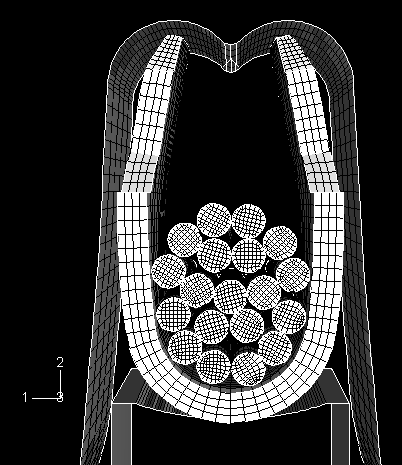
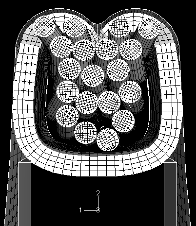
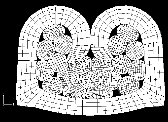
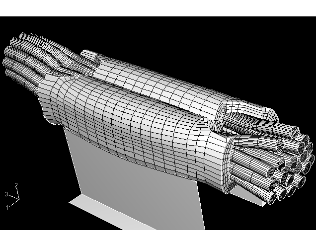
Figure 2.1.10–3 shows the deformed shape of the crimp assembly after the grip arms have reached the roof of the punch (39 milliseconds). Figure 2.1.10–4 shows the deformed shape of the crimp assembly after the grip arms have curved around the roof of the punch and partially folded over into the wire bundle (76 milliseconds). The grip arms buckle between Figure 2.1.10–3 and Figure 2.1.10–4. Figure 2.1.10–5 shows a cross-sectional view of the grip and wire bundle taken at the midlength of the grip. This figure shows the distortion of the wires after 107 milliseconds, when the punch has made a downward stroke of 6.605 mm. Figure 2.1.10–6 shows the final deformed shape of the model (the rigid punch has been removed from the view for clarity). The grip arms have fully folded over into the wire bundle, and the punch has made its complete downward stroke. This figure also shows the out-of-plane extrusion of the wire bundle after distortion.
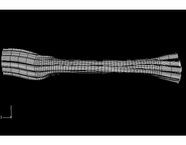
Figure 2.1.10–7 shows the final shape of the wire bundle without the surrounding grip. This figure shows that the originally round wires have been distorted during crimp formation. This distortion is essential for the correct formation of the crimp joint. The bare copper wires are actually covered by a thin layer of brittle copper oxide that forms on exposure of the copper to air. The goal of crimp forming is to break this oxide layer and expose the copper to the surface of the grip by inducing significant surface strains in each wire.
Input data for this analysis.
External file referenced by this analysis.
Villeneuve, G., D. Kulkarni, P. Bastnagel, and D. Berry, “Dynamic Finite Element Analysis Simulation of the Terminal Crimping Process,” 42nd IEEE Holm Conference, Chicago, IL, October 1996.
Villeneuve, G., P. Bastnagel, D. Berry, and C. S. Nagaraj, “Determining the Factors Affecting Crimp Formation Using Dynamic Finite Element Analysis,” 30th IICIT Connector and Interconnection Symposium, Anaheim, CA, September 1997.
Berry, D. T., “Development of a Crimp Forming Simulator,” ABAQUS User's Conference Proceedings, pp. 125–137, 1998.