Product: ABAQUS/Standard

| Young's modulus | 1 × 10⁴ |
| Poisson's ratio | 0.3 |
| C10 (hyperelastic, hybrids only) | 1.9 × 10³ |
| D11 (hyperelastic, hybrids only) | 2.4 × 10⁻⁴ |
| Young's modulus (rebars) | 1 × 10⁶ |
| Poisson's ratio (rebars) | 0.3 |
Loading and boundary conditions:
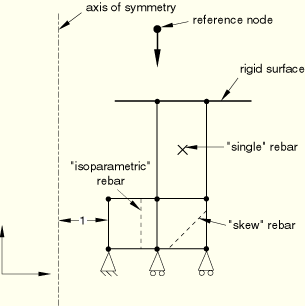
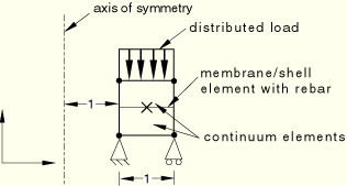
The loading and boundary conditions on the axisymmetric continuum element model are depicted in Figure 3.9.1–1. The loading and boundary conditions on the axisymmetric shell and membrane element model are depicted in Figure 3.9.1–2.
Figure 3.9.1–1 Axisymmetric model with rebars and prescribed loading and boundary conditions for continuum elements.

Figure 3.9.1–2 Axisymmetric model with rebars and prescribed loading and boundary conditions for shell and membrane elements.

The three-dimensional model generated is verified to be correct. The results from the axisymmetric analysis are transferred correctly onto the three-dimensional model.
CAX3 elements; two-dimensional model.
CAX3 elements; three-dimensional model.
CAX3H elements; two-dimensional model.
CAX3H elements; three-dimensional model.
CAX4 with SFMAX1 elements; two-dimensional model.
CAX4 with SFM3D4R elements; three-dimensional model.
CAX4H with SFMAX1 elements; two-dimensional model.
CAX4H with SFM3D4R elements; three-dimensional model.
CAX4I with SFMAX1 elements; two-dimensional model.
CAX4I with SFM3D4R elements; three-dimensional model.
CAX4IH with SFMAX1 elements; two-dimensional model.
CAX4IH with SFM3D4R elements; three-dimensional model.
CAX4R with SFMAX1 elements; two-dimensional model.
CAX4R with SFM3D4R elements; three-dimensional model.
CAX4RH with SFMAX1 elements; two-dimensional model.
CAX4RH with SFM3D4R elements; three-dimensional model.
CAX6 elements; two-dimensional model.
CAX6 elements; three-dimensional model.
CAX6H elements; two-dimensional model.
CAX6H elements; three-dimensional model.
CAX8 with SFMAX2 elements; two-dimensional model.
CAX8 with SFM3D8R elements; three-dimensional model.
CAX8H with SFMAX2 elements; two-dimensional model.
CAX8H with SFM3D8R elements; three-dimensional model.
CAX8R with SFMAX2 elements; two-dimensional model.
CAX8R with SFM3D8R elements; three-dimensional model.
CGAX3 elements; two-dimensional model.
CGAX3 elements; three-dimensional model.
CGAX3H elements; two-dimensional model.
CGAX3H elements; three-dimensional model.
CGAX4 with SFMGAX1 elements; two-dimensional model.
CGAX4 with SFM3D4R elements; three-dimensional model.
CGAX4H with SFMGAX1 elements; two-dimensional model.
CGAX4H with SFM3D4R elements; three-dimensional model.
CGAX4R with SFMGAX1 elements; two-dimensional model.
CGAX4R with SFM3D4R elements; three-dimensional model.
CGAX4RH with SFMGAX1 elements; two-dimensional model.
CGAX4RH with SFM3D4R elements; three-dimensional model.
CGAX6 elements; two-dimensional model.
CGAX6 elements; three-dimensional model.
CGAX6H elements; two-dimensional model.
CGAX6H elements; three-dimensional model.
CGAX8 with SFMGAX2 elements; two-dimensional model.
CGAX8 with SFM3D8R elements; three-dimensional model.
CGAX8H with SFMGAX2 elements; two-dimensional model.
CGAX8H with SFM3D8R elements; three-dimensional model.
CGAX8RH with SFMGAX2 elements; two-dimensional model.
CGAX8RH with SFM3D8R elements; three-dimensional model.
MAX1 elements; two-dimensional model.
MAX1 elements; three-dimensional model.
MAX2 elements; two-dimensional model.
MAX2 elements; three-dimensional model.
MGAX1 elements; two-dimensional model.
MGAX1 elements; three-dimensional model.
MGAX2 elements; two-dimensional model.
MGAX2 elements; three-dimensional model.
SAX1 elements; two-dimensional model.
SAX1 elements; three-dimensional model.
SAX2 elements; two-dimensional model.
SAX2 elements; three-dimensional model.
DSAX1 elements; two-dimensional model.
DSAX1 elements; three-dimensional model.
DSAX2 elements; two-dimensional model.
DSAX2 elements; three-dimensional model.
CAX4T with SFMAX1 elements; two-dimensional model.
CAX4T with SFM3D4R elements; three-dimensional model.
CAX4HT with SFMAX1 elements; two-dimensional model.
CAX4HT with SFM3D4R elements; three-dimensional model.
CAX4RT with SFMAX1 elements; two-dimensional model.
CAX4RT with SFM3D4R elements; three-dimensional model.
CAX8T with SFMAX2 elements; two-dimensional model.
CAX8T with SFM3D8R elements; three-dimensional model.
CAX8HT with SFMAX2 elements; two-dimensional model.
CAX8HT with SFM3D8R elements; three-dimensional model.
CAX8RT with SFMAX2 elements; two-dimensional model.
CAX8RT with SFM3D8R elements; three-dimensional model.
CAX8RHT with SFMAX2 elements; two-dimensional model.
CAX8RHT with SFM3D8R elements; three-dimensional model.
DCAX4 elements; two-dimensional model.
DCAX4 elements; three-dimensional model.
CGAX4T with SFMGAX1 elements; two-dimensional model.
CGAX4T with SFM3D4R elements; three-dimensional model.
CGAX8T with SFMGAX2 elements; two-dimensional model.
CGAX8T with SFM3D8R elements; three-dimensional model.

| Young's modulus | 5 × 10³ |
| Poisson's ratio | 0.3 |
| Young's modulus (rebars) | 2.5 × 10⁵ |
| Poisson's ratio (rebars) | 0.0 |
Loading and boundary conditions:
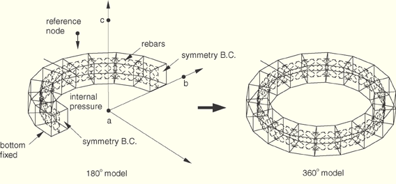
The loading and boundary conditions on the symmetric three-dimensional model are depicted in Figure 3.9.1–3. Internal pressure of 10 units is applied to the cylindrical model, while the top and bottom edges of the cylinder are clamped. The complete three-dimensional model is generated by using the *SYMMETRIC MODEL GENERATION, REFLECT=LINE option to reflect the symmetric three-dimensional model about the axis shown. The symmetric results are read into the complete three-dimensional model as initial conditions using the *SYMMETRIC RESULTS TRANSFER option. Wedge elements are verified without rebars.
The reflected three-dimensional model generated is verified to be correct. The results from the symmetric three-dimensional analysis are transferred correctly onto the reflected three-dimensional model.
C3D6 elements; two-dimensional model.
C3D6 elements; symmetric three-dimensional model, perturbation step with *LOAD CASE.
C3D6 elements; reflected three-dimensional model, perturbation step with *LOAD CASE.
C3D8I elements; two-dimensional model.
C3D8I elements; symmetric three-dimensional model.
C3D8I elements; reflected three-dimensional model.
C3D8R elements; two-dimensional model.
C3D8R elements; symmetric three-dimensional model.
C3D8R elements; reflected three-dimensional model.
C3D15 elements; two-dimensional model.
C3D15 elements; symmetric three-dimensional model.
C3D15 elements; reflected three-dimensional model.
C3D20 elements; two-dimensional model.
C3D20 elements; symmetric three-dimensional model.
C3D20 elements; reflected three-dimensional model.
C3D20R elements; two-dimensional model.
C3D20R elements; symmetric three-dimensional model.
C3D20R elements; reflected three-dimensional model.
S4R elements; two-dimensional model.
S4R elements; symmetric three-dimensional model.
S4R elements; reflected three-dimensional model.
C3D8RT elements; two-dimensional model.
C3D8RT elements; symmetric three-dimensional model.
C3D8RT elements; reflected three-dimensional model.
DC3D8 elements; two-dimensional model.
DC3D8 elements; symmetric three-dimensional model.
DC3D8 elements; reflected three-dimensional model.

Material properties for continuum elements:
Material properties for shell and membrane elements:
| Young's modulus | 1 × 10⁴ |
| Poisson's ratio | 0.3 |
| Young's modulus (rebars) | 2.5 × 10⁵ |
| Poisson's ratio (rebars) | 0.0 |
Loading and boundary conditions for continuum element model:
The loading and boundary conditions on the symmetric three-dimensional model are depicted in Figure 3.9.1–4.
Figure 3.9.1–4 Symmetric and reflected 3-D continuum element model with prescribed boundary conditions.

Loading and boundary conditions for shell and membrane element models:
The loading and boundary conditions on the symmetric model are depicted in Figure 3.9.1–5. The complete three-dimensional model is generated by reflecting the symmetric three-dimensional model about the ![]() –
–![]() plane using the *SYMMETRIC MODEL GENERATION, REFLECT=PLANE option. The symmetric results are read into the complete three-dimensional model as initial conditions using the *SYMMETRIC RESULTS TRANSFER option. Elements S3/S3R, S4R5, S8R5, STRI3, and STRI65 are verified without the *SYMMETRIC RESULTS TRANSFER option. Rebars are not defined in triangular elements.
plane using the *SYMMETRIC MODEL GENERATION, REFLECT=PLANE option. The symmetric results are read into the complete three-dimensional model as initial conditions using the *SYMMETRIC RESULTS TRANSFER option. Elements S3/S3R, S4R5, S8R5, STRI3, and STRI65 are verified without the *SYMMETRIC RESULTS TRANSFER option. Rebars are not defined in triangular elements.
The reflected three-dimensional model generated is verified to be correct. The results from the symmetric three-dimensional analysis are transferred correctly onto the reflected three-dimensional model.
C3D6H elements; two-dimensional model.
C3D6H elements; symmetric three-dimensional model.
C3D6H elements; reflected three-dimensional model.
C3D8H with SFMAX1 elements; two-dimensional model.
C3D8H with SFM3D4R elements; symmetric three-dimensional model.
C3D8H with SFM3D4R elements; reflected three-dimensional model.
C3D8RH with SFMAX1 elements; two-dimensional model.
C3D8RH with SFM3D4R elements; symmetric three-dimensional model.
C3D8RH with SFM3D4R elements; reflected three-dimensional model.
C3D15H elements; two-dimensional model.
C3D15H elements; symmetric three-dimensional model.
C3D15H elements; reflected three-dimensional model.
C3D20H with SFMAX2 elements; two-dimensional model.
C3D20H with SFM3D8R elements; symmetric three-dimensional model.
C3D20H with SFM3D8R elements; reflected three-dimensional model.
C3D20RH with SFMAX2 elements; two-dimensional model.
C3D20RH with SFM3D8R elements; symmetric three-dimensional model.
C3D20RH with SFM3D8R elements; reflected three-dimensional model.
M3D3 elements; symmetric three-dimensional model.
M3D3 elements; reflected three-dimensional model.
M3D4 elements; symmetric three-dimensional model.
M3D4 elements; reflected three-dimensional model.
M3D4R elements; symmetric three-dimensional model.
M3D4R elements; reflected three-dimensional model.
M3D6 elements; symmetric three-dimensional model.
M3D6 elements; reflected three-dimensional model.
M3D8 elements; symmetric three-dimensional model.
M3D8 elements; reflected three-dimensional model.
M3D8R elements; symmetric three-dimensional model.
M3D8R elements; reflected three-dimensional model.
M3D9 elements; symmetric three-dimensional model.
M3D9 elements; reflected three-dimensional model.
M3D9R elements; symmetric three-dimensional model.
M3D9R elements; reflected three-dimensional model.
S3/S3R elements; symmetric three-dimensional model.
S3/S3R elements; reflected three-dimensional model.
S4 elements; symmetric three-dimensional model.
S4 elements; reflected three-dimensional model.
S4R elements; symmetric three-dimensional model.
S4R elements; reflected three-dimensional model.
S4R5 elements; symmetric three-dimensional model.
S4R5 elements; reflected three-dimensional model.
S8R elements; symmetric three-dimensional model.
S8R elements; reflected three-dimensional model.
S8R5 elements; symmetric three-dimensional model.
S8R5 elements; reflected three-dimensional model.
STRI3 elements; symmetric three-dimensional model.
STRI3 elements; reflected three-dimensional model.
STRI65 elements; symmetric three-dimensional model.
STRI65 elements; reflected three-dimensional model.
C3D8HT elements; two-dimensional model.
C3D8HT elements; symmetric three-dimensional model.
C3D8HT elements; reflected three-dimensional model.
DC3D8 elements; two-dimensional model.
DC3D8 elements; symmetric three-dimensional model.
DC3D8 elements; reflected three-dimensional model.

These tests verify the symmetric model generation and results transfer capability for a periodic structure. The *SYMMETRIC MODEL GENERATION, PERIODIC option is used to generate a three-dimensional periodic model by revolving a three-dimensional repetitive sector about a symmetry axis. The bottom surface of the periodic model is fixed, while the top surface of the periodic model is in contact with a pad that is subjected to distributed loadings. If the symmetric surfaces in the original sector have precisely matched meshes, duplicated nodes will be eliminated automatically to ensure that the mesh is connected properly between the neighboring sectors when the original sector is revolved about the symmetry axis to create a periodic model. In all other cases constraints between the automatically generated neighboring pairs of corresponding surfaces are then applied with the automatically generated *TIE option when the original sector is revolved about the symmetry axis to create a periodic model. Both open (the structure has end edges) and closed loop periodic structures are considered. The results from the original sector are transferred to the periodic model using the *SYMMETRIC RESULTS TRANSFER option.
Material properties:
The three-dimensional periodic model generated is verified to be correct, as are the constraints between the neighboring pairs of corresponding surfaces when meshes for the symmetric surfaces are not matched precisely in the original sector. The results from the original sector are transferred correctly onto the periodic three-dimensional model.
C3D8 elements; a single three-dimensional sector with completely matched meshes.
C3D8 elements; periodic three-dimensional model with open end edges; requires smg_wedge.inp.
C3D8 elements; periodic three-dimensional model with closed loop; requires smg_wedge.inp.
C3D8 with S4 elements; a single three-dimensional sector with completely matched meshes.
C3D8 with S4 elements; periodic three-dimensional model with open end edges; requires smg_wedge2.inp.
C3D8 with S4 elements; periodic three-dimensional model with closed loop; requires smg_wedge2.inp.
C3D8 with M3D4R elements; a single three-dimensional sector with completely matched meshes.
C3D8 with M3D4R elements; periodic three-dimensional model with open end edges; requires smg_wedge3.inp.
C3D8 with M3D4R elements; periodic three-dimensional model with closed loop; requires smg_wedge3.inp.
C3D20 elements; a single three-dimensional sector with completely matched meshes.
C3D20 elements; periodic three-dimensional model with open end edges; requires smg_wedge4.inp.
C3D20 elements; periodic three-dimensional model with closed loop; requires smg_wedge4.inp.
C3D8 elements; a single three-dimensional sector with mismatched meshes.
C3D8 elements; periodic three-dimensional model with mismatched meshes and open end edges; requires smg_wedge_mismap.inp.
C3D8 elements; periodic three-dimensional model with mismatched meshes and open end edges; requires smg_wedge_mismap.inp.
C3D8 elements; periodic three-dimensional model with mismatched meshes and closed loop; requires smg_wedge_mismap.inp.
C3D8 elements; periodic three-dimensional model with mismatched meshes and closed loop; requires smg_wedge_mismap.inp.
DC3D8 with DS4 elements; a single three-dimensional sector with completely matched meshes.
DC3D8 with DS4 elements; periodic three-dimensional model with open end edges; requires smg_wedge-d1.inp.
DC3D8 elements; a single three-dimensional sector with mismatched meshes.
DC3D8 elements; periodic three-dimensional model with mismatched meshes and open end edges; requires smg_wedge_mismap-d1.inp.
C3D8T elements; a single three-dimensional sector with mismatched meshes.
C3D8T elements; periodic three-dimensional model with mismatched meshes and open end edges; requires smg_wedge_mismap-t1.inp.

Symmetric model generation and results transfer for models involving large deformation, frictional contact with a curved surface, rebars, embedded elements, and surface elements with rebar layers.
These tests verify the symmetric model generation and results transfer capability for a hyperelastic rubberlike material reinforced by stiff strands. The strands are modeled either as rebars directly in continuum elements, as rebar layers in membrane elements embedded in continuum elements, or as rebar layers in surface elements embedded in continuum elements. The model consists of a Mooney-Rivlin material, and the reinforcing strands are linear elastic. The strands have a cross-sectional area of 0.5 square mm each, are laid in a single layer with a spacing of 5 mm, and are inclined at 50° to the ![]() –
–![]() plane in the axisymmetric model. The reinforced body is then compressed along the
plane in the axisymmetric model. The reinforced body is then compressed along the ![]() -direction by rigid curved surfaces resulting in large deformations in the material. The strands do not lie in the
-direction by rigid curved surfaces resulting in large deformations in the material. The strands do not lie in the ![]() –
–![]() plane; therefore, this compression results in twisting of the material about the axis of symmetry.
plane; therefore, this compression results in twisting of the material about the axis of symmetry.
The *SYMMETRIC MODEL GENERATION, REVOLVE option is used to generate a three-dimensional revolved model from the axisymmetric model, and the results from the axisymmetric analysis are transferred to the revolved model using *SYMMETRIC RESULTS TRANSFER. The three-dimensional revolved model is then reflected through a line using the *SYMMETRIC MODEL GENERATION, REFLECT=LINE option, and the results are transferred to this reflected model using *SYMMETRIC RESULTS TRANSFER.
Material:The undeformed and deformed axisymmetric model is depicted in Figure 3.9.1–6. A displacement of 0.08 has been prescribed to the rigid body reference node along the negative axial direction. A cut-out of the deformed three-dimensional revolved and reflected model is shown in Figure 3.9.1–7. The three-dimensional model and the transferred results are verified to be correct.
CGAX4 elements; axisymmetric model with rebars.
C3D8 elements; three-dimensional revolved model.
C3D8 elements; three-dimensional reflected model.
CGAX4H elements; axisymmetric model with rebars.
C3D8H elements; three-dimensional revolved model.
C3D8H elements; three-dimensional reflected model.
CGAX4RH elements; axisymmetric model with rebars.
C3D8RH elements; three-dimensional revolved model.
C3D8RH elements; three-dimensional reflected model.
CGAX4 elements; axisymmetric model with rebar layers in embedded membranes.
C3D8 elements; three-dimensional revolved model.
C3D8 elements; three-dimensional reflected model.
CCL12 elements; three-dimensional revolved model.
CCL12 elements; three-dimensional reflected model.
CGAX4H elements; axisymmetric model with rebar layers in embedded membranes.
C3D8H elements; three-dimensional revolved model.
C3D8H elements; three-dimensional reflected model.
CCL12H elements; three-dimensional revolved model.
CCL12H elements; three-dimensional reflected model.
CGAX4RH elements; axisymmetric model with rebar layers in embedded membranes.
C3D8RH elements; three-dimensional revolved model.
C3D8RH elements; three-dimensional reflected model.
CGAX4 elements; axisymmetric model with rebar layers in embedded surface elements.
C3D8 elements; three-dimensional revolved model.
C3D8 elements; three-dimensional reflected model.
CCL12 elements; three-dimensional revolved model.
CCL12 elements; three-dimensional reflected model.
CGAX4H elements; axisymmetric model with rebar layers in embedded surface elements.
C3D8H elements; three-dimensional revolved model.
C3D8H elements; three-dimensional reflected model.
CCL12H elements; three-dimensional revolved model.
CCL12H elements; three-dimensional reflected model.
CGAX4RH elements; axisymmetric model with rebar layers in embedded surface elements.
C3D8RH elements; three-dimensional revolved model.
C3D8RH elements; three-dimensional reflected model.